Degrees of Freedom of members and joints of mechanisms govern the working of a machine. Each member of mechanism can move in certain directions or rotate about certain axes and is not allowed to move or rotate in other directions. Degrees of Freedom determine the possible movements of mechanisms.
Kinematic Definition
Degrees of freedom (DoF) is related to the motion possibilities of rigid bodies. Kinematic definition for DoF of any system or its components would be “the number of independent variables or coordinates required to ascertain the position of the system or its components”.
The concept of DoF in kinematics of machines is used in three ways. DoF of
-
A body relative to a reference frame.
-
A kinematic joint.
-
A mechanism.
Determining Degrees of freedom
Degrees of Freedom can be determined by analysis of motion of the concerned body or by determining the number of coordinates required to specify position of the body. In this article planar cases are considered which can be extended to spatial cases.
1. Degrees of freedom of a body relative to a specified reference frame
In a plane the position of a body relative to a reference frame can be specified by two position coordinates (say X and Y) and one coordinate (say theta)for specifying the orientation of the body. Total three coordinates are required to specify the position of the body if there are no constraints applied. The DoF will reduce as the motion of the body is restricted.
For example, a body is not allowed to move along one axis in the plane. As a result one DoF if lost thus leaving only two DoF.
2. Degrees of freedom of a kinematic joint
Two bodies connect with each other to form a joint. One body can move in a number of ways relative to the other and may be constrained in other ways. DoF of a kinematic joint is number of ways in which one member of the joint can move relative to the other member.
For example, revolute joint has one DoF as one member can move only in one way relative to the other member. It can only rotate about the axis of the joint. Prismatic joint also has only one DoF as one of the two members can slide along the other in one direction only.
Cylindrical joint has two DoF as one of the two members can rotate about the axis of the joint and can also translate along it. Two motions possible so two DoF.
3. Degrees of freedom of a mechanism
The DoF for a mechanism is defined as the number of coordinates or variables required to be specified such that the position and orientation of all the members of the mechanism can be stated as a function of time.
For determining the DoF for a mechanism we will start with assuming all the members of the mechanism free in plane and thus having three DoF each. Then we will apply constraints and DoF will reduce as the members are joined together to form mechanism.
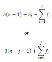
Take the mechanism to be composed of ‘n’ members or links. Initially each link is assumed to be free and thus the mechanism has 3n DoF. One of the members is to be a base or frame link thus have zero DoF or it lost its all three DoF. The DoF left in the mechanism at this stage is 3n-3 or 3(n-1).
When the pairs of links form joints they will loose DoF. If the formed joint have ‘Fi’ DoF each then reduction in DoF is (3-Fi) as they were initially free (having 3 DoF). If there are ‘j’ number of joints then total reduction in DoF will be summation of (3-Fi) over ‘j’ number of joints . The net DoF for a mechanism can be given by
This post is part of the series: Kinematics - Design of Mechanisms
Machines as simple as livers, machines such as James Watt’s steam engine and the industrial robots such as PUMA all are composed of mechanisms whether simple, complex or combination of many simple and complex mechanisms. These mechanisms are governed by Kinematics – the study of geometry and motion.
- Kinematics - Design of Mechanisms: Introduction
- Analysis and Synthesis in Machine Design
- Types of Kinematic Joints
- Degrees of Freedom
- Kinematics – Design of Mechanisms: Kinematic Inversion
- Kinematics – Actuation of Machines: Part I – Electrical Actuation
- Kinematics – Actuation of Machines: Part II – Hydraulic Actuation
- Kinematics – Actuation of Machines: Part III – Pneumatic Actuation
- Kinematics - Analysis of Mechanisms: Methods and Techniques
- Kinematics - Synthesis of Mechanisms: Methods and Techniques
- Four Bar Linkages in Machine Design
- Straight Line Mechanisms
- Kinematics - Special Mechanisms: Straight Line Mechanisms - II
- Exact Straight Line Mechanisms


