In continuance to the last article, which gave introduction about some special mechanisms and briefly explained Watt’s straight line mechanism, in this article few more approximate straight line mechanisms will be discussed. These are different configurations of four bar linkages.
Chebyshev’s Straight Line Mechanism
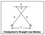
The Chebyshev approximate straight line mechanism is also a four bar linkage mechanism that is both historically important and also of practical importance. After the invention of steam engine and straight line mechanism by Watt a range of straight line mechanisms were designed. Chebyshev’s mechanism is the first mechanism to be designed after Watt’s linkage by a Russian Mathematician Pafnuty Chebyshev. This mechanism was invariable used for linear guidance of the piston and valves.
Like the Watt’s Linkage Chebyshev’s straight line mechanism is simple in construction. It is a double rocker and the mid point of the coupler is the point tracing the approximate linear path. Chebyshev’s mechanism has two critical advantages over Watt’s linkage, viz, a very long segment of the path of the coupler midpoint is approximately linear and both fixed points of the linkage are on the same side of the linear path, which in case of Watt’s linkage are on opposite sides. The required proportions of the length of members of the linkage are a = 1, b = 2.5 and c = 2.
Robert’s Straight Line Mechanism
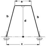
Like the Chebyshev’s mechanism Robert’s approximate straight line mechanism is a symmetrical four bar linkage. The construction of Robert’s mechanism is different from the approximate straight line mechanisms discussed so far, in the sense that, this mechanism has an extension to the coupler at the coupler mid point. this extension is perpendicular to the line joining the two adjacent joints. The end point of the coupler extension generates an approximate straight line for the motion between the fixed pivots.
This mechanism designed by Richard Robert has the proportions of lengths of members of the linkage as, a = 1, b = 1.2, c = 2 and d = 1.09. This approximate straight line mechanism is generally used for linear guidance of the tracing point. The point required to traverse on straight line is constrained to the end point of the coupler extension. Robert’s straight line mechanism is normally used in the coupler driven mode, that is, the mechanism is not driven by either of the cranks or rockers instead the coupler extension is used to just guide the requisite point along an approximate straight line.
This post is part of the series: Kinematics - Design of Mechanisms
Machines as simple as livers, machines such as James Watt’s steam engine and the industrial robots such as PUMA all are composed of mechanisms whether simple, complex or combination of many simple and complex mechanisms. These mechanisms are governed by Kinematics – the study of geometry and motion.
- Kinematics - Design of Mechanisms: Introduction
- Analysis and Synthesis in Machine Design
- Types of Kinematic Joints
- Degrees of Freedom
- Kinematics – Design of Mechanisms: Kinematic Inversion
- Kinematics – Actuation of Machines: Part I – Electrical Actuation
- Kinematics – Actuation of Machines: Part II – Hydraulic Actuation
- Kinematics – Actuation of Machines: Part III – Pneumatic Actuation
- Kinematics - Analysis of Mechanisms: Methods and Techniques
- Kinematics - Synthesis of Mechanisms: Methods and Techniques
- Four Bar Linkages in Machine Design
- Straight Line Mechanisms
- Kinematics - Special Mechanisms: Straight Line Mechanisms - II
- Exact Straight Line Mechanisms


