Like structural constraints in structural FEA, we can simulate thermal constraints in thermal FEA using pro mechanica.
We can simulate three types of thermal constraints in pro mechanica, these are:
Prescribed Temperature: In structural FEA, you basically apply load to some surface/edge/point and then try to constraint the body by fixing or limiting the displacement of some other surface, similarly in thermal FEA you have to apply heat load at some area of the body and temperature constraints to some other area.
By clicking insert > prescribed temperature or by the icon you will be able to reach the prescribed temperature dialogue box.
The dialogue box is more or less similar to the heat load definition dialogue box, here also you have to name the constraint as well as the set or you may go for creating new set as well.
By clicking the advanced button you will get a field named spatial distribution, where different available are uniform, function of coordinate and interpolated over entity. I have already discussed these options earlier.
Please use a consistent unit throughout the analysis, if you want to change the unit system then go to applications > standard and then follow with edit > setup > unit.
Convection Conditions
There are three ways heat can transfer namely, conduction , convection and radiation .
Conduction is the transfer of energy where atoms take part and no movement of the particles is required. Heat transfer from one end of a solid to the other is an example of this type.
In Convection he particles need to be moved from a hotter place to a cooler place to transfer heat, this typically takes place in liquids and gases.
Radiation does not require any media to transfer heat from source to receiver.
So, in pro mechanica you will think of applying convection conditions when there are contacts between solids and fluids.
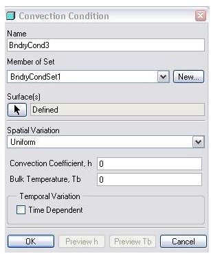
You can either go to insert > convection conditions or click on the related icon to open the convection condition dialogue box (refer to the attached picture). You have to specify the name and load set, as well as define the reference entities where you want to apply these thermal boundary conditions.
Then you have to specify the spatial variation, it may be:
- Uniform — Use this option to apply a convection coefficient and bulk temperatures that are uniform over the entity.
Additionally, the following options are available for shell and solid surfaces in 3D models:
-
External Conv Coefficient — Imports a convection condition FNF file that contains an externally calculated or measured convection coefficient that can vary spatially over the selected surface(s).
-
External Bulk Temperature — Imports a convection condition FNF file that contains an externally calculated or measured bulk temperature that can vary spatially over the selected surface(s).
-
External Conv Coefficient & Bulk Temperature — Imports a convection condition FNF file that contains an externally calculated or measured convection coefficient and bulk temperature, both of which can vary spatially over the selected single or multiple surfaces.
What is FNF file?
FEA neutral format file is the full form of FNF file. It is having .fnf file extension and is used for importing external load or constraints data .It is having specified format. We will discuss more about the FNF file later on.
Convection Coefficient (h): Incase you are not using an externally defined convection coefficient file, you have to specify it. It determines how much heat will transfer between the solid and its contact fluid. It is equal to the heat transfer per unit time per unit area/length/volume per degree temperature difference. Please ensure the consistent system unit.
Bulk Temperature (Tb): Incase you are not using an externally defined bulk temperature file, you have to specify it. Bulk temperature is the temperature of the surrounding fluid.
Pro mechanica uses the following equation to calculate convection heat transfer rate:
Q=h (Te-Tb)
Where,
Q= convection heat transfer rate
h= convection heat transfer coefficient
Te= Temperature of entity (temperature of solid surface/curve/point)
Tb= bulk temperature (temperature of fluid)
Symmetry Constraints
In thermal FEA you can simulate only cyclic symmetry and not mirror symmetry.
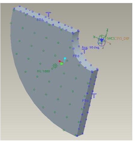
In cyclic symmetry you have to model a certain angular segment of the whole model and the whole model should be generated if we revolve one of the symmetry surfaces by a certain angle. Please refer the attached picture.
Click insert > symmetry constraint to open the cyclic symmetry dialogue box. You have to specify two surface about which the model segment cyclic symmetric, in the picture I have specified two flat surface for this purpose. Of course you have to give name and load set before specifying the surfaces.
This post is part of the series: Pro-Mechanica Tutorial
Pro-mechanica is a FEA module of pro-engineer. If you complete reading this series and do practice as required then you will be able to do analysis using pro-mechanica, of course you should have basic knowledge of pro-engineer or other 3D cad package.
- Pro-Mechanica Tutorial Part 1: Introduction to FEA
- Pro-Mechanica Tutorial Part 2: AutoGEM & Meshing
- Pro-Mechanica Tutorial Part 3: Structural Loads
- Pro-Mechanica Tutorial Part 4: Thermal Loads
- Pro-Mechanica Tutorial Part 5: Thermal Constraints
- Pro-Mechanica Tutorial Part 6: Structural Constraints
- Pro Engineer Mechanica Tutorial Part 7: Analysis and Design Studies
- Pro-Mechanica Tutorial Part 8: Reviewing FEA Results


