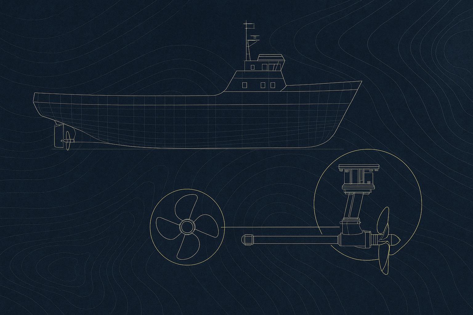
Centrifugal pumps have been used in industry for a hundred and fifty years or more. They are used to convert the energy from the pump driver to kinetic and potential energy into the fluid, via the impeller. They are used aboard ships to circulate seawater and freshwater cooling for the main engine.
A ship’s engine room contains several different types of pumps including centrifugal pumps. In the next few sections, the maintenance of centrifugal pumps is explained. Here we will have a look at the procedure to strip, inspect and reassemble a centrifugal pump, forming part of the planned maintenance schedule on board ships for the purpose of maintaining the equipment in optimum operating condition.
The first section gives an overview of a typical centrifugal pump operation
Overview
As we saw earlier; the centrifugal pump was developed in the mid 1800’s, although it was used in a crude form before then. The main design change was by John Appold in 1851; he replaced the impeller straight vanes by curved blades.
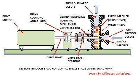
The pump converts mechanical energy from the drive to kinetic energy, with this being transferred to the fluid as pressure.
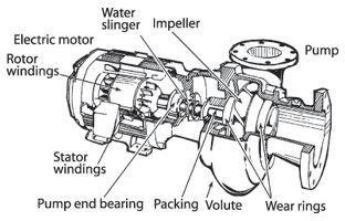
This takes place due to the two main components of the pump: the impeller and the volute. The rotating impeller converts the input of mechanical energy to kinetic energy, while the stationary volute converts this to pressure.
The fluid to be pumped enters the pump through the suction pipe nozzle, where it is drawn directly to the impeller “eye” located in the center of the impeller. The impeller spins the fluid tangentially and radially with centrifugal force outwards. The curved blades create a low pressure at the eye that allows more fluid to be drawn from the suction nozzle to the impeller.
So basically, the pump operates on the transfer of mechanical energy from the drive motor from where it is converted to kinetic energy that is transferred to the fluid as pressure energy. The rotation of the impeller with its curved vanes draws the fluid from the suction nozzle; throwing it outwards, expelling it through centrifugal force from the discharge nozzle.
A sketch of a horizontal pump is shown below.
Removal of Pump for Inspection and Maintenance
1 Isolate pump electrical circuit breaker on main switch board and attach a warning notice. (Do Not Operate-Men at Work).
2. Switch off and lock pump supply at its local supply panel. Attach a warning notice to pump local supply panel.
3. Close suction and discharge valves, chain and lock hand wheels.
4. Open pump suction and discharge pipe drain valves to bilge and when water ceases to flow; crack open the pipes / pump flange joints carefully to ensure that pump has drained off and is safe for opening.
5. Fix a shackle to lifting pad eye above pump and hang chain block; ensuring SWL of block, slings and shackles are satisfactory.
6. Use a center-punch to match/mark coupling and casing, then remove the coupling bolts.
7. Disconnect, fix i/d tag and remove motor supply cables; taping over bare ends with insulating tape.
8. Connect shackle and sling to motor eyebolt and lift motor clear of pump using overhead chain block. Lay motor on its side out of harm’s way, protecting machined surfaces on both pump and motor coupling halves against damage. (Cardboard and masking tape is quick and efficient method.)
9. Disconnect all external fittings from pump casing e.g. cooling pipe, pressure gauge, oil reservoirs and air cock.
10. Remove bolting from top cover and remove cover. Scrape off old gasket and check mating surfaces, and renew gasket on assembly. (Light smear of grease on gasket / faces)
11. The pump shaft with impeller can be lifted out of casing.
12. Dismantle the impeller, and remove the wear ring.
13. Remove the gland packing and disregard; replacing it on rebuild. Remember to cut ends of packing at 45° and stagger joints when repacking gland.
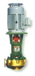
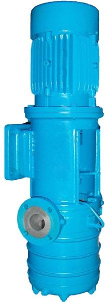
Centrifugal Pumps Fitted on Board (Images Taken from National Center for Appropriate Technology Website)
Inspection Procedure for Pump and Motor
Pump
1. Impeller, pump shaft and internal volute/casing can now be inspected for erosion, pitting and wear.
2. If required rectify pitting or erosion in the impeller and casing with two – part alloy epoxy putty. (See my article in the Reference section)
3. Check main drive shaft bearings and thrust bearings for wear and replace if required.
4. Check wear ring clearance using feeler gauges; in my day at sea it was general practice is to replace with new rings at major overhaul.
5. Check impeller / shaft key and keyways for damage and undue wear, Unscrew impeller shaft securing nut and check threads are in satisfactory condition; retighten to manufacturers torque settings.
6. Give all parts a good clean removing any dirt/ medium residue before re- assembly using new parts as required.
7. Enter date of overhaul and parts renewed in the pump maintenance record card.
Drive Motor
1. Grip motor drive shaft /coupling firmly and check for excess axial and longitudinal movement. Rotate shaft at speed by hand, allowing it to run to a stop whilst listening for excess noise from bearings. Any doubt on either counts, the bearings should be replaced.
2. Megger check motor windings to ensure no dampness is present and windings are in good condition. Any suspect readings indicate a full motor strip to check condition of rotor and stator.
3. If these checks are satisfactory, grease bearings as required. Some bearings are now sealed for life and will not require greasing.
Procedure to Start the Pump
1. Unlock and remove chains from inlet/outlet valve wheels and open both valves full.
2. Open air cock and expel air from line and pump while checking for any leaks
3. Turn the shaft coupling and ensure shaft is free to rotate.
4. Reconnect motor.
5. Remove danger notices from pump power supplies and reinstate breakers.
6. Start and record current drawn by the motor under starting and running conditions. Check and record the discharge pressure.
References
- gouldspumps: Mechanical seals
- Willie Scott: Use of epoxy alloy resins
- Pacificliquid: Centrifugal Pump Operation