Turbocharger is a unique machine that uses the exhaust of an engine to provide an extra charge of air to the engine cylinders. Lets take a look at its constructional features and working principles.
Introduction
The previous article described what is turbocharging and why is it important to the marine engines . This article closely describes the constructional characteristics and working features of a turbocharger, explaining in detail as to how the engine exhaust drives the turbine and how the compressor reciprocates to its motion.
Turbocharger Design
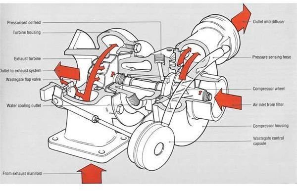
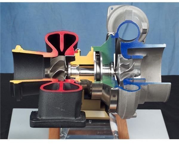
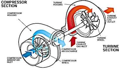
A turbocharger is basically a combination of a compressor and a turbine, both mounted on a common shaft. Turbocharger uses the exhaust gases of the engine itself, to rotate the turbine which in turn moves the compressor.
Mainly two type of compressors are used in a turbocharger.
- Centrifugal compressors
- Axial flow compressors
Centrifugal compressors are generally used in applications where the size of turbocharger is to be kept small, for e.g., turbocharger in automotive system.
Axial flow compressors are used in applications of larger radial units where internal modifications might be needed. They are most efficient with engines using heavy oils.
Main Parts
There are three main parts of a turbocharger :
- Turbine
- Impeller / Compressor
- Central Hub
The wheels of the turbine and compressor are contained in their own conical housing. The amount of air that is to be submitted depends on the sizes of these wheels. The shaft is contained in the central hub with the help of bearings and connects the turbine and impeller wheel on the opposite sides. Due to high speed of rotation, extreme heat is generated in the hub. Water cooling or any other form of cooling system is provided to prevent temperatures from rising.
Sufficient sealing arrangements are made between the compressor and turbine side to prevent mixing of gases. A filter is provided on the turbine side to ensure that the air going to the compressor side is free of any impurities.
Turbine Side
The turbine side is usually made of cast iron material. The inlet side of the turbine have nozzle blade ring which is used for two purposes -
- To guide the incoming gas onto the turbine wheel
- To house the turbine bearings
The outlet side of the turbine casing consists of blower and air passages to supply air to labyrinths seals.
Compressor Side
The compressor side is usually made of aluminum alloys and it also consists of two parts. The inlet part or casing deals with drawing air from the surrounding areas i.e engine room or deck spaces. If air is drawn from the deck spaces, special ducting is made for the same. The advantage of drawing air from the deck spaces is low air temperature and humidity. While the advantage of drawing air from the engine space is that the air is pressurized and there is no need for long and complex ducting arrangements.
The main parts on the compressor side are inducer, impeller, diffuser and inlet and outlet casing.
Working
The turbine uses energy from the exhaust gases to convert heat energy into rotational motion. This rotational motion of turbine drives the compressor, which draws in ambient air from the surrounding and pumps compressed air with high density and pressure into the intake manifold.
The exhaust gas enters the turbine inlet side of the turbocharger through a pressurized chamber and a series of filters. The nozzle blade rings concentrates the exhaust gas on to the turbine wheel. The movement of the turbine wheel rotates the shaft which in turn rotates the impellor of the compressor. A part of this air goes to the labyrinths seal from the outlet side of the turbine.
As the impeller rotates, air is sucked in through the center of the impeller and due to the heavy rotational movement, experiences circumferential velocity which pushes it outwards. A radial velocity is gained which pushes the air further outwards on to the inducer. An additional resultant velocity is gained due to the accurately designed inducer inlet angle which gives maximum compressor efficiency.
Excessive pressure leads to spoiling or fouling of the impeller and inducer surfaces. This results in change in angle of incidence and thus drop in efficiency.
All heavy fuel engines are subjected to heavy load variations which results in fluctuation of exhaust gas pressure. A prolonged fluctuation in pressure leads to detrimental effects on the internal parts of the compressor. For this reason, constant pressure chambers are provided in most of the engines. The exhaust gas, instead of directly entering from the engine, first goes to the pressure chamber and from there it is circulated to the turbine at constant pressure. This reduces the excessive stress that gets created on the shaft bearing and sealing. We will learn about turbocharger surging in our next article.
References
Introduction To Marine Engineering - 2nd Edition by D.A Taylor
Image Credits
https://www.lotusespritturbo.com/Garrett _AiResearch_T3_Turbocharger.jpg
https://www.paxmanhistory.org.uk/images/turbochr.gif
https://upload.wikimedia.org/wikipedia/commons/7/76/Turbocharger.jpg
This post is part of the series: Turbocharger : Construction and Working
This series explains the importance of turbocharger in a marine diesel engine. Learn the construction and working of a turbocharger and also the operational difficulties attached with it.