Excel spreadsheets for overall heat transfer coefficient calculations in U.S. units or S.I. units can be downloaded from this article. This type of calculation is needed as part of the iterative heat exchanger design process.
Background
Heat exchanger design is an iterative process. At the beginning an estimated value of the overall heat transfer coefficient, U, is needed, based on the type of heat exchanger and the fluids involved. Information about the fluid temperatures, flow rates, and properties allows determination of the required heat transfer rate, Q, and the log mean temperature difference, ΔTlm. Then, using the heat exchanger design equation, Q = UAΔTlm, allows an initial calculation of the needed heat transfer area, and then choice of a preliminary configuration for the heat exchanger can be made (e.g. pipe diameters and length for a double pipe heat exchanger or number and size of tubes for a shell and tube heat exchanger). At this point, a more detailed estimate of the overall heat transfer coefficient can be made, as described in this article. For more details on the overall heat exchanger design process, see the articles in this series like, “Fundamentals of Heat Exchanger Theory and Design ,” and “Preliminary Heat Exchanger Design Example .”
Equations for the Overall Heat Transfer Coefficient
The overall heat transfer coefficient for a heat exchanger depends upon the convective heat transfer coefficient between the hot fluid and the heat
transfer surface, the thermal conductivity and thickness of the heat transfer surface, and the convective heat transfer coefficient between the heat transfer surface and the cold fluid. Emphasis in this article will be on a cylindrical shape for the heat transfer surface, as in a shell and tube or double pipe heat exchanger. The general principles can be applied to heat exchangers of other shapes as well.
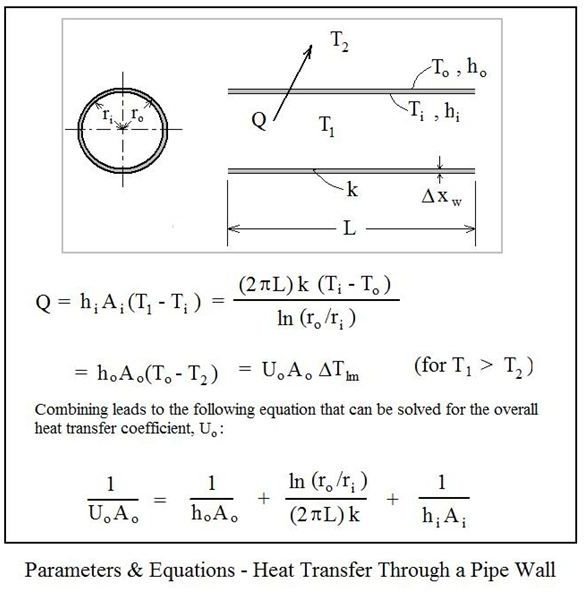
The diagram at the right shows a sketch of a heat transfer tube or pipe with the parameters and equations that lead to an equation for the overall heat transfer coefficient:
1/UoAo = 1/hoAo + ln(ro/ri)/(2πLk) + 1/hiAi
In view of the accuracy of the correlations for estimation of ho and hi, the heat transfer tube or pipe is often treated as a ’thin-walled tube’ with Ao, Ai, and Am [ = 2πL(ro - ri)/ln(ro/ri) ]. The equation above then simplifies to:
1/U = 1/h****o + (r****o - ri)/k + 1/h****i (Note that the thickness of the tube wall, ro - ri, is represented by the symbol ΔXw in the diagram at the right.)
This equation gives an estimate for the overall heat transfer coefficient, U, for a new heat exchanger, or one with newly cleaned heat transfer surfaces. As a heat exchanger is used and fluids flow past the heat transfer surface, both sides of that heat transfer surface tend to accumulate a coating that slows down the rate of heat transfer. This is called fouling of the heat transfer surface. The resistance to heat transfer added by the fouling of the surface is typically accounted for by adding a fouling resistance for each side of the heat transfer surface, Rfo and Rfi to the equation above to give the following:
1/U = 1/h****o + Rfo + (r****o - ri)/k + 1/h****i + R****fi. This is the equation that will be used in the Excel spreadsheets in the next section.
Excel Spreadsheets for Estimation of an Overall Heat Transfer Coefficient
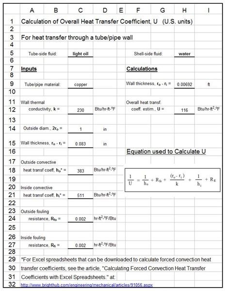
The Excel spreadsheet shown in the image at the left is set up to calculate the overall heat transfer coefficient, U,
based on the indicated input values, which are: the wall thermal conductivity, k; the outside diameter of the tube, 2ro; the tube wall thickness, ro - ri; the outside convective heat transfer coefficient, ho; the inside convective heat transfer coefficient, hi; the outside fouling resistance, Rfo; and the inside fouling resistance, Rfi.
The Excel formulas are set up to calculate the overall heat transfer coefficient, U, using the equation discussed in the previous section:
1/U = 1/h****o + Rfo + (r****o - ri)/k + 1/h****i + Rfi.
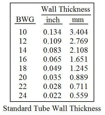
Values for the tube dimensions should be available from preliminary heat exchanger design calculations, which could be done using Excel spreadsheets like those available from the articles, “Excel Spreadsheet Templates for Preliminary Heat Exchanger Design ,” and “Excel Formulas for Pressure Drop in Shell and Tube Heat Exchanger Design .” The table at the upper right gives BWG (Birmingham Wire Guage) wall thicknesses for heat exchanger tubes, which typically have diameters between 1/4" and 2".
The inside and outside convective heat transfer coefficients could be determined from the Excel spreadsheets that can be downloaded from the article, “Calculation of Forced Convection Heat Transfer Coefficients with Excel Spreadsheets .”
Typical fouling resistance values for various combinations of fluids, temperatures and velocities are given in reference #1 below. Most of the fouling resistance values fall between 0.0005 and 0.01 ft2-oF-hr/Btu. For many common heat exchanger situations, the fouling resistance will be between 0.001 and 0.005 ft2-oF-hr/Btu.
The overall heat transfer coefficient calculated in the example Excel spreadsheet shown above turned out to be 116 Btu/hr-ft2-oF, which is amazingly close to the initial ‘rough estimate’ of 120 Btu/hr-ft2-oF, made in the article, “Preliminary Heat Exchanger Design Example several months ago!”
The example Excel spreadsheet uses U.S. units, however the spreadsheet template can be downloaded below with U.S. units or with S.I. units.
Click here to download this Excel spreadsheet in U.S. units .
Click here to download this Excel spreadsheet in S.I. units .
References
References for Further Information:
1. Wolverine Tube Heat Transfer Data Book - has tables of typical fouling resistance values and tables of typical overall heat transfer coefficient values.
2. Bengtson, H., Fundamentals of Heat Exchangers , an online, continuing education course for PDH credit.
3. Kakac, S. and Liu, H., Heat Exchangers: Selection, Rating and Thermal Design, CRC Press, 2002.
4. Kuppan, T., Heat Exchanger Design Handbook, CRC Press, 2000.
This post is part of the series: Heat Exchanger Design
Heat exchanger design includes estimation of the heat transfer area needed for known or estimated heat transfer rate, overall heat transfer coefficient and log mean temperature difference. The tube or pipe diameters and length also need to be determined, as well as the pressure drop.


