Excel formulas for calculation of frictional pressure drop in shell and tube and double pipe heat exchanger design can be downloaded from this article. The pressure drop calculation is for the tubes in a shell and tube heat exchanger or for the inside pipe in a double pipe heat exchanger.
Preliminary Heat Exchanger Design Background
Heat exchanger design is a multi-step, iterative process made up of the following steps:
- Calculate the heat transfer rate, Q, in Btu/hr, based on specified information about fluid flow rates and temperatures.
- Determine an estimated value for the overall heat transfer coefficient, U, based on the fluids involved.
- Calculate the log mean temperature difference, ΔTlm, using the inlet and outlet temperatures of the two fluids.
- Make an initial estimate of the heat transfer area required, using: A = Q/(U ΔTlm).
- Choose a preliminary configuration for the heat exchanger and make necessary calculations (e.g. number and size of tubes in a shell and tube heat exchanger or pipe diameters and length for a double pipe heat exchanger).
- Estimate the pressure drop across the heat exchanger. If it is too high or too low, revise the configuration of the heat exchanger until the pressure drop is acceptable.
- Make a more detailed estimate of the overall heat transfer coefficient, U, based on the current configuration of the heat exchanger.
- If the latest estimate of U is significantly different than the previous estimate, repeat steps 4 through 7 as many times as necessary until the two estimates are the same to the desired degree of accuracy.
More details about this process are available in the first two articles of this series, “Fundamentals of Heat Exchanger Theory and Design ,” and “Preliminary Heat Exchanger Design Example .”
Background on Pressure Drop Calculation for Pipe Flow
The most widely used equation for frictional head loss or frictional pressure drop in pipe flow (and the equation used in the Excel formulas in this article’s spreadsheet templates) is the Darcy Weisbach equation:
hL = f(L/D)(V2/2g) or in term of pressure drop: ΔPf = ρghL = ρf(L/D)(V2/2), where
- hL = frictional head loss, ft-lb/lb
- L = pipe length, ft
- D = pipe diameter, ft
- V = average flow velocity of fluid (= Q/A), ft/sec
- g = acceleration due to gravity = 32.2 ft/sec2
- f = friction factor, a dimensionless empirical factor that is a function of Reynolds Number (Re = DVρ/μ) and/or ε/D, where
- ε = an empirical pipe roughness, ft
- ΔPf = frictional pressure drop, lb/ft2
- ρ = fluid density, slugs/ft3
More details about the Darcy Weisbach equation, the parameters used in it, a table of pipe roughness (ε) values for typical pipe materials, typical values for friction factor, f, and equations and graphs for friction factor f as a function of Re and ε/D are available in the article, “Pipe Flow Calculations 3: The Friction Factor & Frictional Head Loss .”
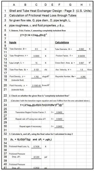
Excel Formulas for Pressure Drop Calculation in Shell and Tube Heat Exchanger Design
The Excel spreadsheet template at the left will calculate the frictional head loss and frictional pressure drop across the tubes of a shell and tube heat exchanger for the flow of the tubeside fluid. The parameters that need input values are the tube diameter and length; the tube roughness; the number of tubes; the tubeside flow rate; and the density and viscosity of the tubeside fluid. The Excel formulas in the spreadsheet template will then caclulate the cross-sectional area for the tubeside fluid flow through the tube bank, the average velocity, the Reynolds number, and an initial estimate of the friction factor. An iterative set of calculations is then used to calculate a value for the friction factor. Then the frictional head loss and the frictional pressure drop are calculated using the Darcy Weisbach equation.
Excel spreadsheet templates that carry out the first 5 steps of the preliminary heat exchanger design process given above for a shell and tube heat exchanger are discussed in, and can be downloaded (in U.S. and S.I. versions) from, the article, “Excel Spreadsheet Templates for Preliminary Heat Exchanger Design .” The Excel spreadsheets that can be downloaded below include the spreadsheet portion shown above plus the portion that carries out the first 5 steps of the design process, so many of the inputs needed for calculation of frictional head loss/pressure drop can be calculated in the first part of the spreadsheet.
Click here to download this Excel spreadsheet template in U.S. units .
Click here to download this Excel spreadsheet template in S.I. units .
Excel Formulas for Pressure Drop Calculation in Double Pipe Heat Exchanger Design
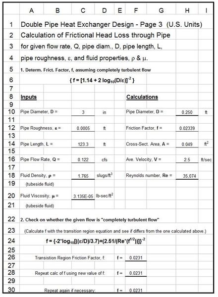
The first part of this Excel template is shown on the left and the second part on the right
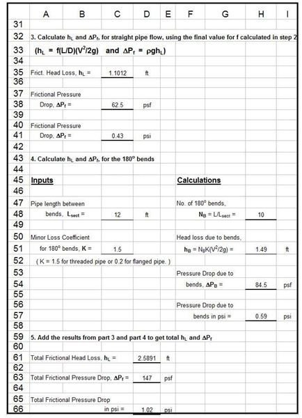
. It will calculate the frictional head loss and frictional pressure drop for the flow through the inside pipe of a double pipe heat exchanger. The parameters that need input values are diameter and total length of the inside pipe; the pipe roughness; the flow rate through the inside pipe; the pipe length between bends; and the density and viscosity of the fluid flowing through the inside pipe. The Excel formulas in the spreadsheet calculate the frictional head loss and pressure drop due to the straight pipe flow in much the same manner as in the shell and tube spreadsheet just discussed above. For the double pipe heat exchanger design, however, there is an additional section for calculation of the ‘minor losses’ due to all of the 180o bends. The two components are then added together to get the total frictional head loss and pressure drop.
As discussed above for the shell and tube heat exchanger design spreadsheet, the Excel spreadsheet templates that can be downloaded below contain the spreadsheet portions for the first 5 steps of the preliminary design procedure, as well as the portions shown in the images in this section.
Click here to download this Excel spreadsheet template in U.S. units .
Click here to download this Excel spreadsheet template in S.I. units.
References
References for Further Information:
1. Munson, B. R., Young, D. F., & Okiishi, T. H., Fundamentals of Fluid Mechanics, 4th Ed., New York: John Wiley and Sons, Inc, 2002.
2. Bengtson, H., Excel Spreadsheets for Preliminary Heat Exchanger Design.
3. Bengtson, H., Fundamentals of Heat Exchangers , an online, continuing education course for PDH credit
This post is part of the series: Heat Exchanger Design
Heat exchanger design includes estimation of the heat transfer area needed for known or estimated heat transfer rate, overall heat transfer coefficient and log mean temperature difference. The tube or pipe diameters and length also need to be determined, as well as the pressure drop.


