Kaplan Turbine is designed for low water head applications. Kaplan Turbine has propeller like blades but works just reverse. Instead of displacing the water axially using shaft power and creating axial thrust, the axial force of water acts on the blades of Kaplan Turbine and generating shaft power.
Most of the turbines developed earlier were suitable for large heads of water. With increasing demand of power need was felt to harness power from sources of low head water, such as, rivers flowing at low heights. For such low head applications Viktor Kaplan designed a turbine similar to the propellers of ships. Its working is just reverse to that of propellers. The Kaplan Turbine is also called as Propeller Turbine.
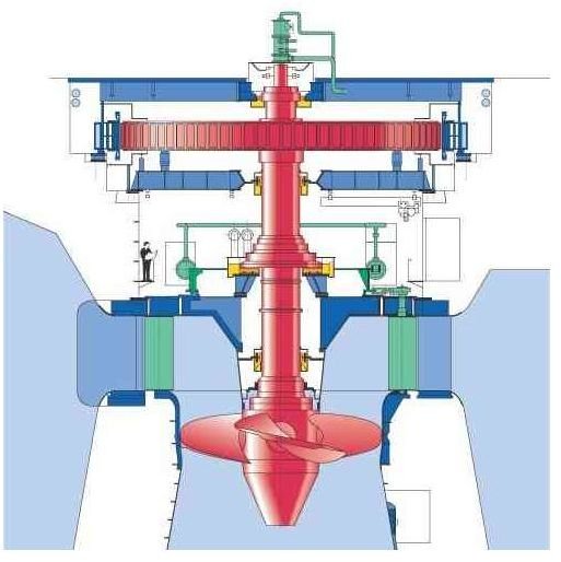
Design of Kaplan Turbine
To generate substantial amount of power from small heads of water using Kaplan Turbine it is necessary to have large flow rates through the turbine. Kaplan Turbine is designed to accommodate the required large flow rates. Except the alignment of the blades the construction of the Kaplan Turbine is very much similar to that of the Francis Turbine. The overall path of flow of water through the Kaplan Turbine is from radial at the entrance to axial at the exit. Similar to the Francis Turbine, Kaplan Turbine also has a ring of fixed guide vanes at the inlet to the turbine.
Unlike the Francis Turbine which has guide vanes at the periphery of the turbine rotor (called as runner in the case of Francis Turbine), there is a passage between the guide vanes and the rotor of the Kaplan Turbine. The shape of the passage is such that the flow which enters the passage in the radial direction is forced to flow in axial direction. The rotor of the Kaplan Turbine is similar to the propeller of a ship. The rotor blades are attached to the central shaft of the turbine. The blades are connected to the shaft with moveable joints such that the blades can be swiveled according to the flow rate and water head available.
The blades of the Kaplan Turbine are not planer as any other axial flow turbine; instead they are designed with twist along the length so as to allow swirling flow at entry and axial flow at exit.
Working of the Kaplan Turbine
The working head of water is low so large flow rates are allowed in the Kaplan Turbine. The water enters the turbine through the guide vanes which are aligned such as to give the flow a suitable degree of swirl determined according to the rotor of the turbine. The flow from guide vanes pass through the curved passage which forces the radial flow to axial direction with the initial swirl imparted by the inlet guide vanes which is now in the form of free vortex.
The axial flow of water with a component of swirl applies force on the blades of the rotor and looses its momentum, both linear and angular, producing torque and rotation (their product is power) in the shaft. The scheme for production of hydroelectricity by Kaplan Turbine is same as that for Francis Turbine.
This post is part of the series: Hydraulic Turbines
Hydraulic Turbines transfer the energy from a flowing fluid to a rotating shaft. Turbine itself means a thing which rotates or spins. To know more about what are Hydraulic Turbines, what is the working principle of Hydraulic Turbines and how are they classified, read on through this article series.


