In a Pelton Turbine or Pelton Wheel water jets impact on the blades of the turbine making the wheel rotate, producing torque and power. Learn more about design, analysis, working principle and applications of Pelton Wheel Turbine.
Hydraulic Turbines are being used from very ancient times to harness the energy stored in flowing streams, rivers and lakes. The oldest and the simplest form of a Hydraulic Turbine was the Waterwheel used for grinding grains. Different types of Hydraulic Turbines were developed with the increasing need for power. Three major types are Pelton Wheel, Francis and Kaplan Turbine.
Design of Pelton Wheel Turbine
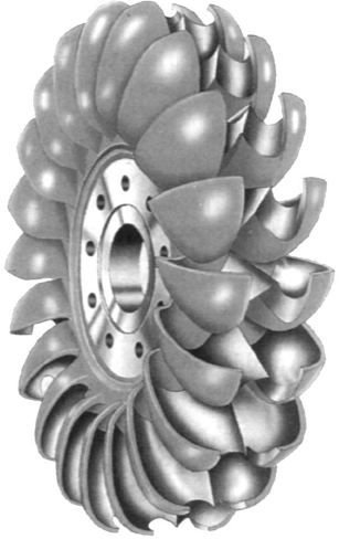
The Pelton Turbine has a circular disk mounted on the rotating shaft or rotor. This circular disk has cup shaped blades, called as buckets, placed at equal spacing around its circumference. Nozzles are arranged around the wheel such that the water jet emerging from a nozzle is tangential to the circumference of the wheel of Pelton Turbine. According to the available water head (pressure of water) and the operating requirements the shape and number of nozzles placed around the Pelton Wheel can vary.
Working Principle of Pelton Turbine
The high speed water jets emerging form the nozzles strike the buckets at splitters, placed at the middle of a bucket, from where jets are divided into two equal streams. These stream flow along the inner curve of the bucket and leave it in the direction opposite to that of incoming jet. The high speed water jets running the Pelton Wheel Turbine are obtained by expanding the high pressure water through nozzles to the atmospheric pressure. The high pressure water can be obtained from any water body situated at some height or streams of water flowing down the hills.
The change in momentum (direction as well as speed) of water stream produces an impulse on the blades of the wheel of Pelton Turbine. This impulse generates the torque and rotation in the shaft of Pelton Turbine. To obtain the optimum output from the Pelton Turbine the impulse received by the blades should be maximum. For that, change in momentum of the water stream should be maximum possible. That is obtained when the water stream is deflected in the direction opposite to which it strikes the buckets and with the same speed relative to the buckets.
Pelton Turbine Hydroelectric Setup
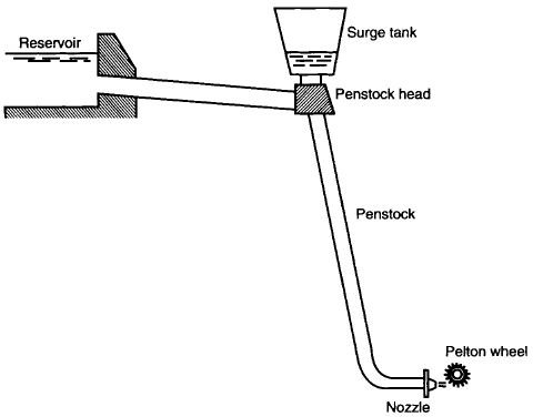
A typical setup of a system generating electricity by using Pelton Turbine will have a water reservoir situated at a height from the Pelton Wheel. The water from the reservoir flows through a pressure channel to the penstock head and then through the penstock or the supply pipeline to the nozzles, from where the water comes out as high speed jets striking the blades of the Pelton Turbine. The penstock head is fitted with a surge tank which absorbs and dissipates sudden fluctuations in pressure.
For a constant water flow rate from the nozzles the speed of turbine changes with changing loads on it. For quality hydroelectricity generation the turbine should rotate at a constant speed. To keep the speed constant despite the changing loads on the turbine water flow rate through the nozzles is changed. To control the gradual changes in load servo controlled spear valves are used in the jets to change the flow rate. And for sudden reduction in load the jets are deflected using deflector plates so that some of the water from the jets do not strike the blades. This prevents over speeding of the turbine.
This post is part of the series: Hydraulic Turbines
Hydraulic Turbines transfer the energy from a flowing fluid to a rotating shaft. Turbine itself means a thing which rotates or spins. To know more about what are Hydraulic Turbines, what is the working principle of Hydraulic Turbines and how are they classified, read on through this article series.


