The simple and easy to build light fader circuits included here will specially interest the new electronic hobbyists. These light control circuits will not only explain its proposed function, but the readers will also get an opportunity to learn about the components involved.
LED Light Fader Design
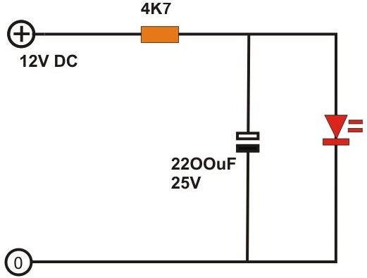
A simplest form of a LED light fader circuit can be designed by just connecting a high value capacitor across a LED (see figure). Since the circuit is very basic cannot produce an effective rise and decay of the LED light. Here, on applying the voltage, the capacitor charges almost instantly and the LED also lights up immediately. Thus, the slow rise in the intensity of the LED cannot be identified. However, when the supply is switched off, the LED extinguishes slowly due to the stored charge inside the capacitor. So the effect is only one sided and also not very efficient as the required capacitor is of a very large value.
Referring to the second figure, we find that the results and the efficiency of the above circuit can be improved quite a lot by adding a transistor and a diode to it.
The working of this circuit can be understood with the following points:
When power is switched ON, capacitor C1 charges almost instantly as there’s no “obstruction” in its path.
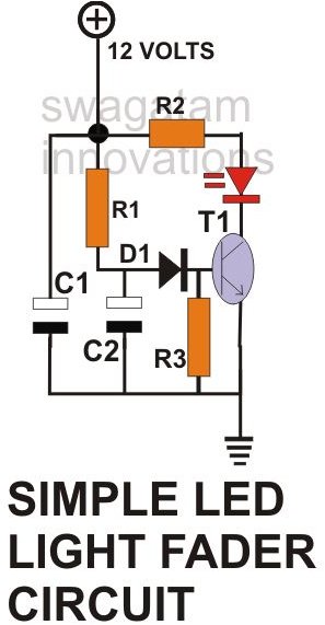
However, capacitor C2 charges very slowly due the “obstruction” or resistance offered by R1.
Now since transistor T1 requires 0.6 volts to fully saturate and light up the LED fully, and because its base is connected to the junction of R1 and C2, this potential is reached only gradually as C2 charges. Therefore the connected LED also lights up correspondingly i.e. gradually.
The above potential of 0.6 volts is not very high and is reached pretty fast as C2 reaches past this voltage at a fairly easy rate.
To prolong the response a bit more, so that the LED lights much slowly, we introduce a diode D1 in the path of T1’s base.
Since a diode also requires a forward voltage of about 0.6 volts, it means, now it would require a total minimum voltage of 1.2 volts to actually make T1 conduct and the LED to reach its full brightness.
Increasing this margin makes it sure that the glow produced in the LED is much gradual and takes a fair bit of time to make it fully illuminated.
Now, if we switch off the power, the charge stored in C1 does not allow the LED to switch off instantly, instead it slowly discharges through D1 and T1 again making the LED die out at the desired slower rate.
Thus this light control circuit very efficiently is able to make a peculiar enhancing entry and a fading exit to the glow of the LED.
AC Incandescent Lamp Fader
In one my previous articles we have discussed regarding the functioning of AC dimmer switch . We studied that in a dimmer switch; the intensity of the connected lamp can be simply increased by decreasing the resistance of its potentiometer and vice versa.
It thus implies that by replacing the potentiometer by a LDR and by making the value of LDR change gradually, the change in the intensity of the lamp can be made correspondingly gradual.
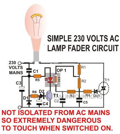
The circuit explained in the above section works on DC and is able to control an LED. Let’s see how we can use this circuit to get the same response but this time with an AC incandescent lamp.
Referring to the adjoining circuit diagram (click to enlarge), we see that the potentiometer in a normal dimmer switch is replaced by a homemade opto-coupler . Here the opto-coupler LED is integrated with the circuit explained in the previous section.
Now everything becomes very simple to understand. The moment we switch ON the power, as explained above, the LED starts getting brighter slowly – the resistance of the LDR correspondingly lowers down causing the lamp at the output to glow brighter at the similar rate (gradually). When the power is switched OFF, the procedure repeats, but in the opposite way and the lamp dies down just very slowly.
All the above explained light control circuits can be easily built over a general purpose PCB with the help of the given circuit schematic. If you have any doubts, please do comment (comments need moderation and may take time to appear).
Parts List
Parts For LED DC Light Fader
R1 = 100 K,
R2 = 1 K,
R3 = 10 K,
C1, C2 = 1000 µF/25V,
T1 = BC 547 B,
D1 = 1N4007,
Parts For Incandescent AC Lamp Fader
R1 = 15 K,
R2 = 330 K,
R3 = 33 K,
R4 = 56 Ω,
R5 = 1 K,
R6 = 68 K,
C1 = 105/400V PPC,
C2, C5 = 68 n/ 250V,
C3, C4 = 1000µ/25V,
D1, D2 = 1N4007,
DC = Diac DB3,
Tr1 = Triac BT136
OP1 = LED/LDR assembly inside a light proof enclosure.


