Electrical testing and measurement devices can tell you if a circuit or wire is energized as well as tell you how much voltage or current an electrical circuit is carrying. Other types of testing devices can tell you if a network cable is connected properly or if there is continuity in that cable.
There are many different types of electrical measuring and testing devices. Some of these test for the presence of electrical current, whether alternating current or direct current. Others test for whether or not an electrical receptacle is properly wired. Electrical measuring devices can be either analog or digital. Some of these measuring devices only measure current, voltage, or resistance, while others will measure all of these circuit or device characteristics. Network technicians rely on tools called modtaps and toners and probes. All of these tools will be described below and you will also be given some easy to follow instructions on how to use them.
Tools That Test for the Presence of Electricity
This type of electrical testing device alerts the user to the presence of electricity with an audible tone, lights, or both. One of the simplest versions of this type of tool consists of two leads, one black and the other red, connected to a handle with an AC/DC light in the handle. This tool must be physically connected to the circuit to work.
The most popular and safe tool that tests for the presence of electrical current is the inductive electrical tester, more commonly known as a tick tracer. This tool gives both a visual signal and an audible tone. The tone is where the name tick tracer is derived. This tool only needs to be within a certain distance of a wire carrying an electrical current in order to sense the current. How it works is that all electrical current creates a magnetic field around the conductor. The tick tracer detects this magnetic field. Since you don’t have to make physical contact with the circuit, you have much less chance of being shocked.
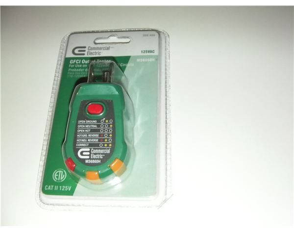
There is also type of testing device that electricians find indispensable that will tell you whether an electrical receptacle/outlet is properly wired. This tool is plugged into the receptacle, and lights correspond to whether or not the receptacle is properly wired.
Electrical Measuring Devices-Analog
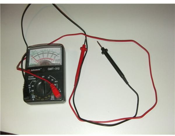
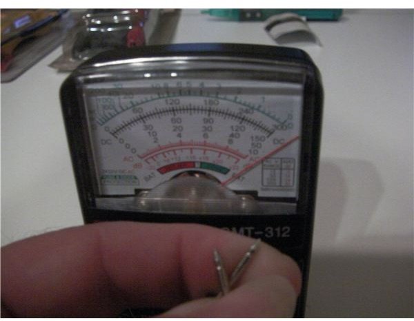
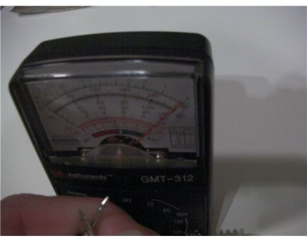
Electrical measuring devices are more commonly referred to as meters. Analog meters can either measure one circuit value (current, voltage, and resistance), or they can measure all of these. Meters that measure multiple types of characteristics are called multimeters. An analog meter has a needle that swings one way or another to indicate the value being measured. A resistance meter reads in reverse. What this means is that no needle swing indicates an open circuit, or infinite resistance. Typically, an analog resistance meter must be calibrated to zero ohms resistance every time it is used to obtain optimal accuracy. Older analog meters will usually only have three settings, one for each value they measure. Newer meters will have multiple scales from which to choose, since an analog meter’s measurements are more accurate when the needle is in the middle of the scale.
Analog Multimeter
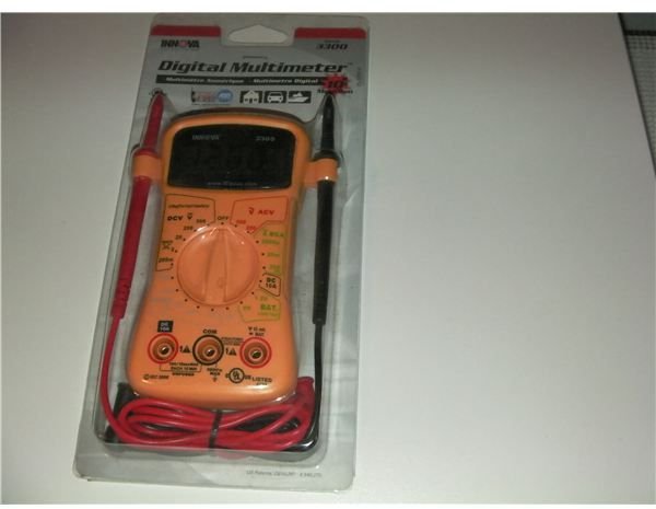
Electrical Measuring Devices-Digital
Like analog meters, digital meters can test one value, or they can test a combination of values. Also, some of these only have three settings- current, voltage, and resistance- while more advanced meters have different scales for each of the three types of values. Some meters (usually lower cost handheld units) are accurate to within two or three decimal places, while others, usually expensive desktop or bench-top meters, can measure out to as many as ten decimal places. Some have rotary dials to select type of value and range, while others are pushbutton operated. There are also meters that combine these two features, with the dial selecting the reading type and the buttons selecting the range. More expensive meters also have settings to audibly test for continuity, capacitance, and inductance, and some specialty meters also have the ability to test transistor junctions. There are also meters that have special settings for testing alkaline batteries.
Measuring Circuit or Component Values
Measuring circuit or components values is fairly easy. Current must be measured open-circuit. What this means is that the meter must be inserted into the circuit in order to measure the current. However, you need to have an idea of how much current you expect to be present in the circuit because most meters can normally only handle a maximum of ten amps. There are some meters that have an unprotected current probe position, but this won’t give as accurate a measurement and there are meters designed for higher currents (these are discussed below).
When measuring voltage, you need to measure across the device being tested, with the red lead toward the power supply and the black towards the ground. Lastly, when measuring resistance, you need to completely de-energize the circuit or you will cause damage to the meter. This is because when the meter is set to measure resistance, it sends a measured voltage through the device being measured. When measuring the resistance of a component in circuit, you need to make sure that you use reverse polarity on any diodes in the circuit, otherwise the current being generated by the meter may go through the circuit and cause an erroneous reading.
Clamp-Type Meters
This type of meter is designed for measuring higher currents without putting either you or your meter at risk of shock. Some of these meters only measure current, while others measure voltage and resistance as well. Voltage and resistance are measured the same way as with any other type of meter. The difference is that current is measured by clamping the meter’s clamps over the power cable with the meter switch(es) set to current. Some meters of this type are capable of reading from zero to a few thousand amps, while most clamp-type met
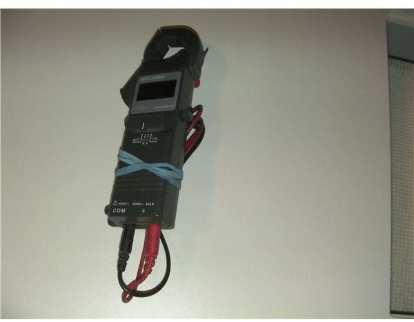
ers will read as high as 100 amps.
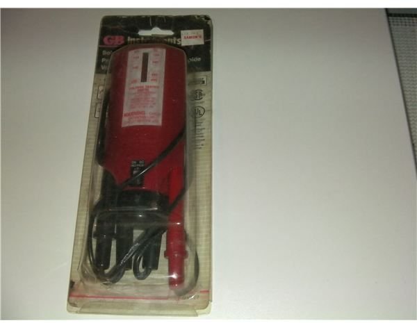
Solenoid Voltage Meter
This type of meter only reads voltage, both for alternating and direct current. However, the ranges this type of meter is able to read are from 120 to 600 volts. When voltage is detected, a solenoid moves an indicator up or down a graduated scale, which indicates the amount of voltage present in the circuit. It’s used in exactly the same way as an analog or digital meter is used when measuring voltage. This is an indispensable part of an electrician’s toolkit, and we call them wiggies.
Network Cable Testing Tools
Network technicians have need of a completely different set of electrical testing tools.
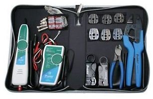
The first of these is the toner and probe combination. The toner is a tone generator and it creates a 1 kilohertz signal, which can be injected onto a wire, either by a telephone jack or with alligator clips. The probe will pick up this tone by induction. Network technicians usually use this tool set to identify a particular network cable in a cable bundle.
Another type of test tool that a network technician uses is called a modtaps. This is used to test an installed network cable and make sure that it’s properly terminated and is a two-piece test set. The two portions of the tool are plugged into the wire at either end, a button is pressed, and lights on the master unit light up to indicate continuity and proper wiring.
References
- All images are of the author’s own tools and are provided by the author. All rights reserved.
- Mike Aguilar has over five years experience as an avionics technician and aviation electrician’s mate in the Navy. He is also a certified electrician and holds a number of network technician certifications.