Basically in an electronic dimmer switch for incandescent lights, a triac forms the main part of the circuit and is responsible for the intensity control of the lights through phase control. Let’s learn more about its functional details and how to build it.
Introduction
In simple words a dimmer switch may be described as a device that can be used to control the speed of an AC operated fan or an incandescent lamp. Thus, every house or an office which has a fan ought to have a dimmer switch wired with it. Though a dimmer switch is mostly operated in conjunction with a ceiling fan, it may also be effectively used to control or vary the light intensity of an incandescent light bulb. Here we will learn how simple it is to build a dimmer switch for incandescent lights, but first let’s try to understand how a dimmer switch actually functions.
How Does The circuit Function?
In one my previous articles we discussed the general principle of operation of electronic dimmer switches . We know that electronic dimmer switches normally work on a principle called phase chopping or phase control that is done through a fast electronic switch triac.
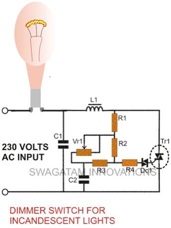
Referring to the figure, triac Tr1 forms the heart of the circuit. A triac is an active electronic component consisting of three terminals: the anode, the cathode, and the gate. A triac will fire only when it receives a gate voltage and will continue to conduct (voltage from its anode to cathode) as long as the gate voltage persists. A lapse in its gate voltage will mean a consequent break in the voltage from its anode to cathode. Note that this is true only for alternating voltages. A diac D1, which is also an active electronic component, is connected to the gate of Tr1 and is commonly used as a complementary device to a triac. It supplies the required gate voltage to the triac, provided the voltage across it has reached its minimum firing voltage level (approximately around 30 Volts). With the help of the given circuit schematic and the following points, let’s try to understand how specifically the circuit of a dimmer switch functions.
In an alternating voltage which is applied to the circuit, as the initial half cycle crosses the zero mark and proceeds towards the peak value, at a certain point capacitor C1 is allowed to become fully charged. Due to this, the diac fires, forcing the triac to conduct and switch ON the lamp. But the triac is able to hold the conduction as long as the AC cycle stays above the point at which the capacitor was allowed to be charged. The moment the AC cycle dips below this point and moves towards the zero crossing, the triac stops conducting and the lamp is switched OFF. This happens for the entire positive and the negative cycles of the alternating voltage. The point in the AC phase at which the capacitor is allowed to be charged and consequently switch ON the triac and the lamp is determined by the setting of VR1. A lower value of VR1 will mean that C1 can get charged much sooner and keep the lamp ON for a larger section of each AC half cycles and vice versa. By changing the value of VR1 we are able to slice down or chop each phase into desired ratios or sections, for which the lamp remains switched ON. As these sections are made shorter, the lamp lights up with less intensity and as the sections gets larger, the lamp brightens. Thus by adjusting VR1 the intensity of the lamp can be varied through the process of phase control.
Parts List
R1 = 22K
R2 = 330K
R3 = 47K
R4 = 47E
VR1 = 680K POT LINEAR,
COIL = 6 AMP. CHOKE
C1 = 104/600V
C2 = 56nF/100V
DB1 = DIAC DB3
TR1 = ANY TRIAC 400V 1KV RATING
Construction Clues
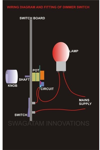
The circuit idea of this dimmer switch for incandescent lights is pretty simple in design. The given components can be easily procured and assembled over a piece of general PCB. The whole assembled unit may be fixed and wired inside your existing domestic switchboard (as shown in the adjoining diagram), allowing only the shaft or the knob of the potentiometer VR1 out of the board so that the intensity of the lamp may be set through it.
Caution: Once connected to the mains supply, the whole circuit will carry dangerous AC mains voltages and can be extremely dangerous. Due precaution is to be maintained.


