The simple home made water level indicator circuit presented in this article is truly straightforward in design incorporating just a handful of components. Once built and attached to your existing over head water tank, it will provide reasonably accurate indications of its level. Read on.
Introduction
In one of my previous articles, I discussed how to build a water level controller . There, we have seen how the proposed circuit is able to control the motor pump by switching it ON and OFF appropriately as per its settings and the water level of the tank to which it has been attached. But there may be folks who would are more interested to personally monitor the tank water level and toggle the motor pump accordingly.The present circuit would benefit them.
The circuit presented here once built and installed will provide quite a satisfactory and reasonably fair indication of the water level present inside the tank through an array of 7 LEDs which are lit sequentially with the rise or fall of the tank water level. The circuit also incorporates a facility of an audio alarm indication in case the tank gets completely filled and is about to overflow. Before we find out how to build a home made water level indicator, let’s first go through its circuit description.
Circuit Diagram and Description
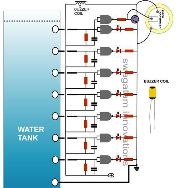
The functioning of the circuit may be understood by referring to the circuit schematic (please click to enlarge) and through the following step by step explanation:
-
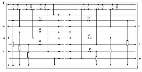
IC 4011 which is a quad 2-input NAND gate, forms the heart of the circuit and is wired as a level monitor.
-
Two such ICs are included to result in 8 NAND gates. Each of these is configured to sense logic differences at their inputs. Since the two inputs of each of the gates are shorted, they also act as inverters and effectively invert any difference in the logic level sensed at their inputs.
-
The output of each gate is connected to an LED. These LEDs are arranged in a straight line to form a sequential array.
-
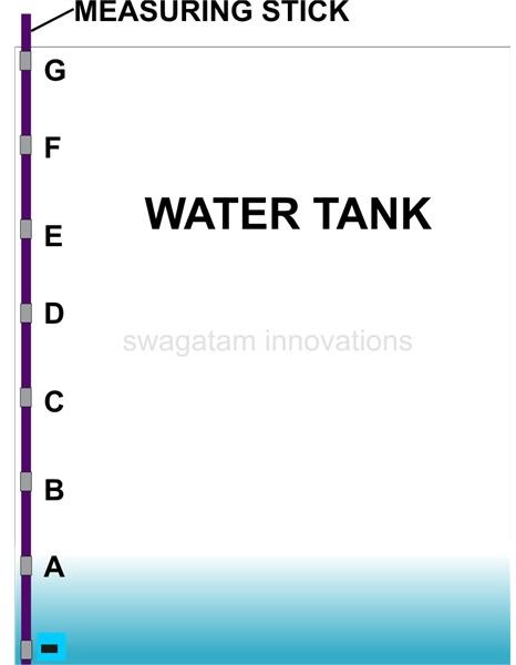
The inputs of each gate are clipped to an external stick in such a way that they cover the entire length of the stick with equal spacing. The length of the stick should exactly match the depth of the tank in question.
-
The bottom most point of the stick is connected to the positive supply.
-
Out of the 8 gates, one has been used to drive a transistor-coil oscillator . When the water touches point G (tank full), the inputs of the gates which are connected to this point go low and their outputs become high. A transistor and a coil assembly connected to its output immediately becomes operative and starts to oscillate. The piezo connected to the transistor also starts vibrating accordingly to produce a sharp buzzing sound for the alarm. The center tap of the piezo provides the required feedback to maintain proper oscillations.
Parts List
All Resistors are 1/4 Watt Unless Otherwise Specified
All resistors connected at the gate inputs are 330K,
All LED series resistors are 2K7,
LED color as per choice,
All Gates are from 2 nos. IC 4011 (Quadruple NAND Gate),
All capacitors 0.1 uF / 50V Ceramic Disc,
Transistor base resistor is 150 K
Transistor BC547 = 1 no,
Buzzer Coil = 1 no,
Piezo Transducer 3-contact = 1 no,
Battery 9V, (A 12 V DC Adapter is Recommended if Used Continuously),
General Purpose Board as Per Size,
Assorted Wire Pack (7/36)
Suitable Plastic Enclosure.
The following construction clues will help you to understand better regarding how to build a water level meter.
Construction Clues
The construction part of this circuit is very straight forward and can be easily finished by fixing the procured electronic components correctly over the general PCB and soldering them with the help of the given circuit schematic.
After completing the PCB assembly, connect the output wires to the appropriate points of the circuit.
Now select a bamboo stick, chisel and carve it properly as per the depth of the water tank. Fix 7 brass screws into it and connect them to the wires terminating from the circuit board appropriately as shown in the circuit diagram. If a bamboo stick is not available then a PVC pipe normally used for electrical wiring will do the job perfectly.
Enclose the circuit board along with the 9volt battery, allowing only the output wires terminating towards the stick. Also remember to stick the piezo as per the instructions on the inner surface of the box.
Insert and fix the stick assembly on the inner surface of the tank, harness out all the wires cleanly up to the main circuit box. The circuit box may be fixed at some suitable safe place on the tank itself or somewhere near to it.
Practical Results
Once the circuit is built and attached to a water tank, it will operate in the following way:
-
Assuming the initial position of the tank to be empty, all the inputs of the gates are kept at logic high by its input resistors.
-
If the tank is now allowed to fill with water, the negative supply at the bottom of the stick gradually connects with the inputs points of the gates one after the other as the water rises.
-
The relevant gates immediately become logic low and go on to activate the output LEDs in a sequential manner.
-
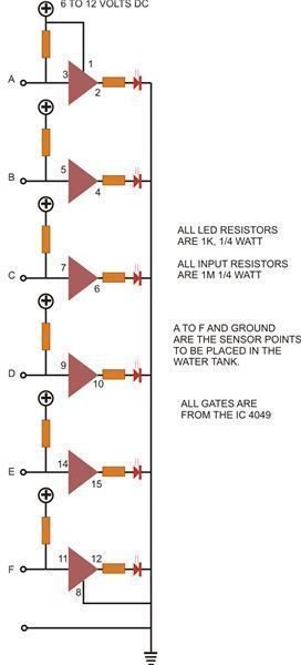
The gate whose input is connected to the top most point of the stick is responsible for activating the alarm once the water level crosses this point.
-
If the water level is allowed to settle at a particular level, the gate input point which is situated exactly below this level on the stick will be held at logic high and its output LED will be illuminated to indicate the appropriate level correctly.
Still have any doubt regarding how to build a water level meter? Jot in your comments (comments need moderation, may take time to appear).
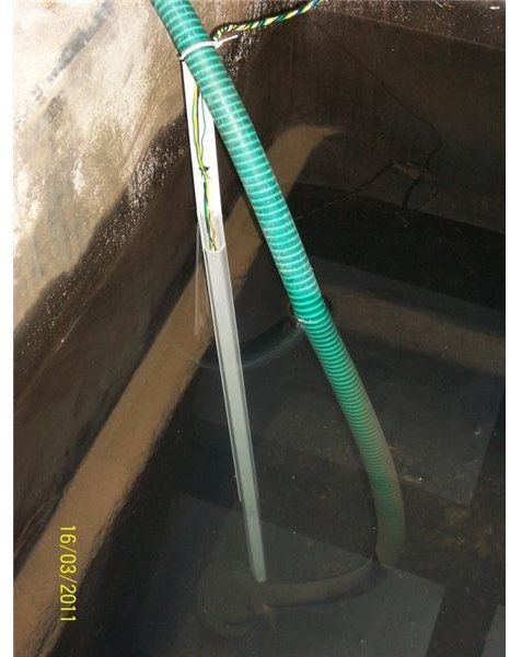
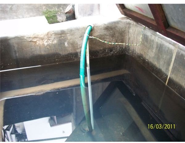
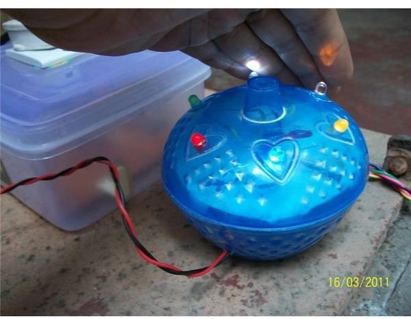
Readers Contribution
Mr. Raj Kumar Mukherji is an electronic enthusiast who likes to read my electronic posts and build them. He successfully built the water level indicator circuit provided in the present article.
However after some discussion the use of 6 NOT gates instead of the NAND gates was preferred as it looked like a better option and was much convenient to build.
The installed prototype is working very well and providing some useful services.
The images and the diagrams depict his success with the project.