Here’s a simple water level controller circuit that you can build and install so that even when you are not around, your home water tank level is maintained automatically.
In most countries houses and buildings tend to have two water tanks, one situated on the roof and another one on the ground or sometimes underground. The received water supply is allowed to fill the lower tank first, and a water pump motor is then switched ON manually so that the water from the lower tank is pumped and shifted into the upper tank on the roof. Once the water from the lower tank is completely transferred into the upper tank, the pump is again manually switched OFF. This process may have to be repeated quite regularly and at times may become a bit of a headache. Moreover in case one forgets or fails to do the manual operations in time, it may result in an overflowing of water and wastage of electricity as well.
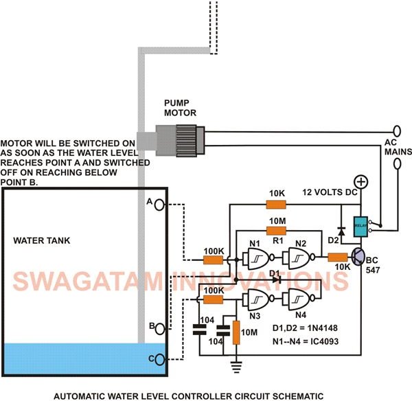
As the name depicts, a water level controller is an automatic device used to monitor a particular level of water (for example in an overhead tank) and restrict it from exceeding the limit. The simple circuit design for such a controller shown here may be easily built and installed and may relieve you from the headache of manually operating the water pump in time.
How Does the Circuit Function?
The heart of the circuit is the single CMOS IC 4093, which solely performs the function of a sensor as well as a controller. In the circuit gates N1 and N2 are rigged into a latch configuration, and its output can be toggled from logic high to a logic low as per the upper level of water. The remaining two gates N3 and N4 are used to switch the output of the latch according to the lower limit of the water in the tank. The operation may be understood in the following manner:
-
Referring to the figure, initially assume that the water level in the tank is below the mark B.
-
At this position the input of N3 is held at logic low by the resistor R2. The output of N4 thus pulls the input of N1 and the output of N2 to a logic low through D1.
-
A logic low at the output of N2 means that the transistor will be unable to activate the relay, keeping the water pump motor connected to the relay contacts shut OFF.
-
Now suppose the tank is allowed to fill by pouring water into it. As soon as the water reaches or crosses point B, the positive supply gets connected through the water to the input point C of N3, making it logic high.
-
Due to this the output of N4 also goes high but does not affect N1 and N2 because of diode D1 and the relay is still unable to energize keeping the pump switched OFF.
-
Now let the water level rise so that it reaches the upper most limits to touch point A, connecting the positive from point B to the input of N1 through the water.
-
Immediately N1 toggles and the output of N2 goes high triggering the transistor and the relay. Consequently the water pump motor is switched ON which starts pulling the water out of the tank.
-
Now as the water is drawn out of the tank, its level will go down. Once it moves below the point A, the positive from point B is cut OFF, but N1 and N2 remains latched because of R1 and the pump continues to run, sucking out the water from the tank.
-
As the water is drained its level falls and the moment it goes below point B, the positive supply is unable to reach point C or the input of N3. It instantly goes logic low; the output of N4 also switches to a logic low, pulling the input of N1 and the output of N2 to a logic low once again.
-
Due to this the transistor loses its base bias, switching OFF the relay and the motor. The circuit is reset to its original position.
Construction Clues

The construction of this water level controller circuit is quite simple and may be easily completed by fixing and soldering the procured electronic components into a small piece of general purpose PCB. Readers may refer to the adjoining pin out diagram of IC4093 for further ease of construction.
The entire assembly, along with the power supply, should be enclosed inside a good looking, sturdy plastic enclosure, allowing only the sensor wires and the mains cord coming out of the box.
The sensor wires may be striped to a length of around 1 inch and fixed using two-compound glue inside a PVC pipe. The position of the sensor wire ends and the length of the pipe will depend on the size and the depth of the tank.
One may comfortably dimension it to set the switching points of the water pump motor with the help of the circuit schematic.
Pin-out image credit: https://www.syntax.com.tw/proddata/IC/IC-4093.JPG
Over Head Tank Water Level Indicator and Motor Protector
The above circuit has been presented on request from one of my followers, Prateek. The A to E wire ends of the circuit are placed in the shown order inside the overhead tank. The level of the water is indicated by the LEDs, which light up as the water climbs inside the overhead tank.
The couple of terminals at F should be placed at the point where water enters the motor pump, located beside the underground tank. The terminal pair must be secured at least an inch apart over a plastic strip, making sure no residual water gets accumulated across these two points when actual water supply is over.
The gates are all from the IC 4049, the input resistors across the input of the gates and the positive are all 1M, rest of the resistors are 1K, the transistor is BC547, relay is 12 V, 400 Ohms, SPDT type.
The supply to the circuit can be made through a 12 volt DC adapter or a transformer, bridge, capacitor network.


