The circuit of a homemade room temperature monitor presented in this article will very accurately display the temperature variations taking place in the environment surrounding it. Learn to build this room temperature sensor with 0 to 10v output.
Introduction
In a previous article we learned how to build a temperature controller , along with its use in various different applications. The circuit utilized a multipurpose, versatile silicon diode 1N4148 as the sensor of the unit.
This diode, like most other semiconductor components, has the serious drawback of changing its basic characteristic in the influence of a varying ambient temperature. But paradoxically, this property in fact has turned into a boon for the construction of various electronic temperature controllers and so this diode can be simply used as a temperature sensor.
Compared to thermistors, silicon diodes are more efficient because of their smaller size and more accurate and consistent response to temperature variations. The only drawback with these components is that they are likely to get damaged at temperatures above 150° Celsius. But this maximum range satisfies most of its application requirements.
The diode 1N4148 is comfortably able to produce a linear and an exponential voltage drop across itself in response to a corresponding increase in the ambient temperature. This voltage drop is around 2mV for every degree rise in temperature.
The circuit of this room temperature monitor also incorporates the same component as the sensing device, and is built around a single IC TL074. Once built and installed in your house, it will provide a reasonably accurate reading of your room’s varying atmospheric temperatures, so that now you can remain informed 24/7 about the minutest temperature changes taking place inside your house.
Let’s proceed and see how the circuit actually functions.
Circuit Description
The circuit may be understood through the following explanation:
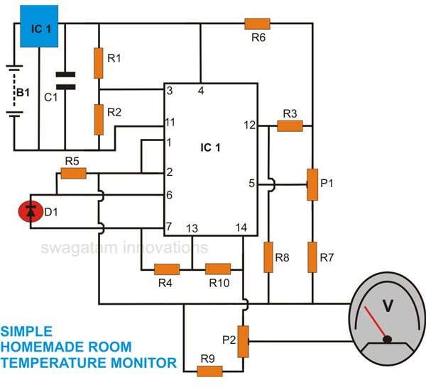
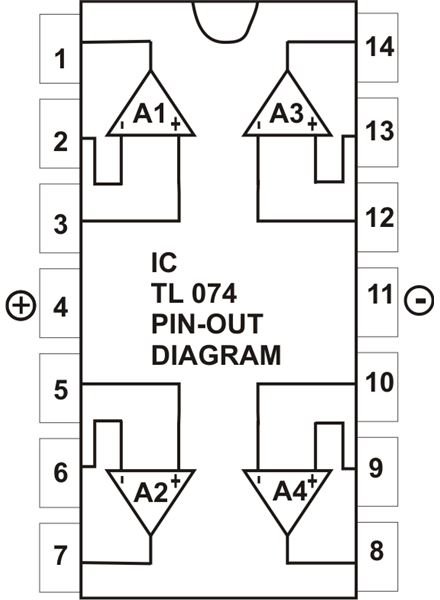
IC2 TL074 is a quad op amp IC and becomes the heart of the circuit. Three of its op amps have been used in the circuit in three different important configurations.
Referring to the figure, we see a constant reference voltage at the non inverting input #3 of A1, which is wired as a voltage follower and buffer. This reference is derived through the potential divider R1/R2.
The buffered reference voltage continues from the output of A1 to the inverting input #6 of A2, which is basically configured as a comparator.
(Click Image to Enlarge)
The voltage at the non inverting input pin #5 of A2 is held at a constant level with the help of resistors R6, R7 and preset P1. This also means that the current through R5 and hence the diode D1 (sensor) is also constant. Any variation of voltage across D1 will be compared and translated into an amplified response by A2 at its output.
As explained earlier, any change in the ambient temperature surrounding D1 will cause an equivalent change in voltage across it. Consequently, this will also result in a change in voltage level across R5, which in turn will be amplified by A2 at its pin #7.
This output voltage at pin #7 will be exactly proportional to the temperature variations sensed by D1.
The third op amp A3 is also rigged as a voltage amplifier and further amplifies the output from A2. Its non inverting input is also kept at a constant voltage level (just like A2).
Before this voltage reaches pin # 12 of A3, it is properly calibrated so that a zero degree Celsius ambient temperature produces exactly zero volts at the output of A3 and goes on increasing proportionately up to its maximum range (100 degree Celsius).
To make the circuit read temperatures below zero degrees Celsius, a symmetrical supply voltage to the circuit is necessary. The special configuration of A1 along with R1, R2 and IC1 plays an important role in enabling this.
In the above configuration, output of A1 creates a constant positive reference voltage relative to the negative supply line and acts as a ground (zero potential) for the remaining part of the circuit. The supply to the whole circuit thus becomes quite symmetrical.
Parts List
You will need the following parts for the construction of this room temperature sensor with 0 to 1v output.
All resistors are ¼ Watt, unless otherwise specified.
R1, R2 = 4K7,
R3, R4, R5 = 1K
R6 = 560Ω,
R7, R9 = 1K8,
R8, R10 = 6K1,
P1, P2 = PRESETS 2K2 LINEAR,
(Click Image to Enlarge)
C1 = 104 DISC,
D1 = 1N4148
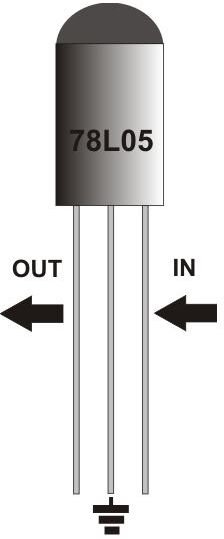
IC1 = 78L05,
IC2 = TL074,
GENERAL PURPOSE PCB = AS PER SIZE,
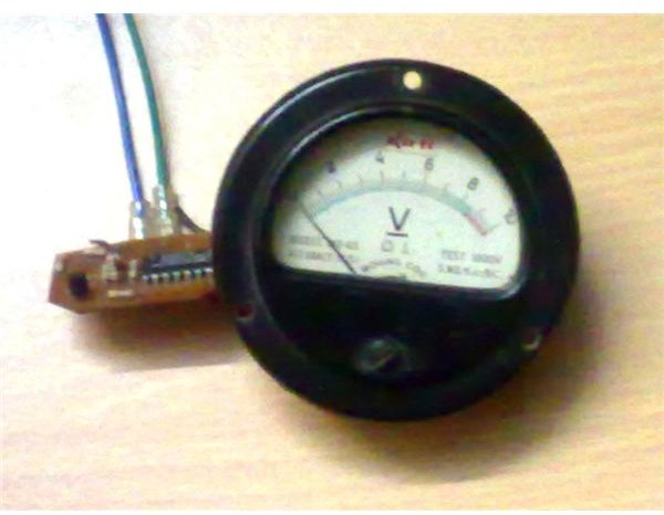
M1 = METER 0 – 1V FSD, MOVING COIL TYPE.
Building the Circuit
The construction procedure of this circuit is simple if you follow these instructions:
(Click Image to Enlarge)
-
Cut the procured general PCB into the required size of around 3 square inches.
-
Insert IC2 somewhere around the middle of the board. Solder all its leads properly.
-
Next, insert the presets at suitable positions around IC2, leaving enough space in between for the other components.
-
In the same way, insert the remaining associated passive components uniformly around IC2, solder and interlink all the connections, following the circuit schematic.
-
Finally, solder IC1 over the PCB, and connect the sensor D1 to the circuit using two small lengths of thin flexible wires.
The current requirement of the circuit is approximately 5mA. If it is intended for incidental uses, a built-in 9 volt battery will serve the purpose quite well. If you want continuous monitoring, the circuit may be powered using an external 12 volt battery eliminator module.
Setting up the unit
To set up the room temperature sensor with 0 to 1V output voltages, follow this procedure step by step:
-
Connect the specified (0 – 1 volts) moving coil type voltmeter to the output of the assembled circuit as shown in the circuit diagram.
-
Remove a couple of ice cubes from your refrigerator in a plastic cup and insert the sensor diode in between the two cubes so that it is totally engulfed between. Wait for a couple of minutes until the ice starts melting.
-
Now switch ON the power to the circuit, and keeping the adjustment of P2 somewhere about midway, start adjusting P1 to get zero volts reading on the meter.
The minimum range setting is complete and you may now remove the sensor from the ice.
- Next, heat a bowl of water until it just starts boiling.
- Dip the sensor into this water and begin adjusting P2 to make the meter read exactly 1 volt (full scale deflection).
The circuit is now fully set and will accurately display ambient temperature variations over the range of minus 10° to 100° Celsius.
You may now cover the whole circuit with a rigid plastic enclosure having enough space for accommodating the circuit as well as the meter. Make sure that the sensor D1 is kept exposed outside, preferably by fitting it on the outer surface of the box using two-compound glue.


