The circuit of an electronic temperature controller presented here requires very few components to build and yet is able to control temperatures at the required levels quite accurately. Learn more regarding the simple design.
Introduction
The electronic temperature controller units which are commonly available in the market are usually quite sophisticated in design and therefore costly. These are more suitable in areas where a precise temperature control may be required. Obviously such hi-end types of control systems may be of no help or too expensive to many electronic hobbyists and in places where the needs are not that specific or critical. Also the cheap types are not reliable at all, because their accuracy is not consistent. The diy temperature controller circuit presented in this article is super simple in design, yet is able to produce reasonably accurate and consistent temperature control over a range of 40 to 125 degrees Celsius, which is fully adjustable.
How Does the Circuit Functions
Every electronic semiconductor component has got a “bad nature” of changing its characteristics in the influence of a varying ambient temperature.
We have studied in one of my previous articles how it becomes important to optimize the current through a zener diode due to the effect of a varying ambient temperature so that its value can be kept constant.
But this particular “bad behavior” of semiconductors has been perfectly exploited in this electronic temperature controller circuit.
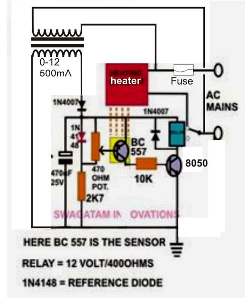
Here the diode 1N4148 is used as a reference to monitor the ambient temperature whereas the transistor
BC557 is configured as a sensor to sense the temperature in question with reference to the ambient temperature.
In the influence of the applied heat, the base emitter voltage of the transistor will drop. The drop of voltage will be around 2mV for one degree of rise in temperature.
Due to this the transistor will gradually start conducting and at a point (as per the setting of P1) will switch ON T2 to activate the relay and the external cooling agent.
Construction Hints
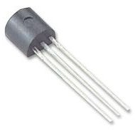
The construction part is very simple as the circuit of this low cost temperature controller requires hardly any components. The procured parts may be simply inserted into a small piece of general purpose PCB and soldered to interconnect their leads.
The whole assembly can be housed inside a sturdy plastic enclosure, allowing only the mains cord and the sensor out of the box. The length of the sensor wire should not be more than a meter long to avoid stray signal pick-ups.
The potentiometer should be fixed over the box so that it can be adjusted externally to set the tripping point as per the applications.
Setting Up the Unit
For setting the unit you will require a digital temperature meter, and may be done through the following simple steps:
-
Plug in the unit to the AC supply; connect its sensor as well as the sensor of the meter to the heating element whose temperature is required to be controlled. Also, connect the heater to the output of the unit, so that now it starts heating up.
-
Monitor the rise in temperature over the digital meter, as soon as it reaches the required tripping point, adjust the potentiometer so that the relay just activates and breaks the supply to the heater.
-
Consequently, the heating element will start cooling down and after a certain period of time its temperature will come down to a level where the relay will restore back the supply to the heating element and the cycle will repeat. This time period will depend upon the hysteresis of the circuit.
Applications
The simple circuit of this low cost temperature controller may be used for the following couple of important applications:
To Protect Power Transistors: In many electronic circuits power transistors perform vital functions of controlling heavy output loads and therefore may get heated up to appreciable limits. Though these are always fitted over aluminum heat sinks for optimum cooling, the temperature at times may cross uncontrollable levels.
The sensor of the present circuit can be integrated to the heat sink and the relay contacts may be wired either to a cooling fan or may be simply used to switch OFF the power so that the heat may not exceed to a damaging limit.
In Poultry Farms: The newly hatched chickens inside poultry farms are very vulnerable to the changing climatic conditions. A proper regulation of the temperature around them thus becomes very essential. Usually hi-power incandescent bulbs are used to keep the inside atmosphere of the poultry farm warm and conducive to the baby chickens, but if the intensity of these bulbs are not controlled, things can get hazardous.
Again, by attaching the sensor of the proposed electronic temperature controller circuit to a particular bulb may be effectively used to switch them OFF in case the ambient temperature rises to a critical point thus helping to keep the average farm temperature to a healthy proportion.
Readers may customize and modify this diy temperature controller circuit as per their own needs and specifications to find its numerous other applications. Just remember to keep the reference diode far away from the temperature which is to be sensed.


