
In a monostable mode, a number of different alarm circuits using 555 timer applications may be designed. Two sample ideas of a rain sensor and a light sensor circuit are described here. Readers will definitely enjoy building these circuits with the help of the given circuit schematics.
Introduction
In one of my previous articles I discussed a few simple circuit ideas using the evergreen, versatile IC 555 . Here we will spend some time with this workhorse IC and learn how to build a couple of easy alarm circuits using 555 timer applications. As explained earlier, the most common mode in which the IC 555 can be configured is in the form of a monostable multivibrator. In this mode the IC remains continuously in an alert standby position. Its pin #2 may be integrated with different sensors to make the circuit detect the relevant parameters and activate an alarm or a countermeasure device connected to its output for averting the sensed danger. The activated alarm may be wired to latch up permanently or switched ON for a fixed predetermined period set by the external timing components. In the monostable mode, the circuit may be rigged into some useful alarm circuits.
About the Circuits
The first circuit described is of a rain sensor which will produce an audible tone the moment it comes in contact with water. Thus it may be used to detect the commencement of rain, so that one may bring the valuable assets like a vehicle or clothes under cover before they are drenched in heavy showers.
The adjoining circuit diagram shows the standard configuration of the IC as a monostable multivibrator. Water in its pure form is a bad conductor of electricity but practically offers a pretty low resistance to an electric current due to the mixed impurities in it. When a stream of water is allowed to flow over the sensor, the bridges become electrically connected. A positive supply is thus able to pass through the water, bypassing the sensor tracks and providing the required base bias to T1. T1 instantly conducts to send a positive trigger to pin 2 of the IC 555. The IC toggles to activate the load at its output. The time for which the monostable remains activated will depend on the value of C1 and the setting of P1.
(Click Image to Enlarge)
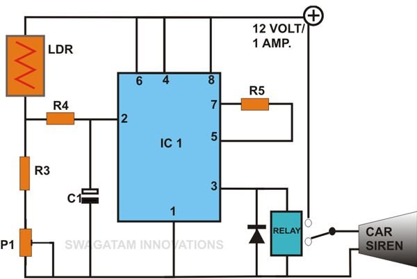
The light sensor circuit shown in the adjoining diagram is also configured as a standard monostable. Here an LDR forms the sensor and replaces the water sensor as described in the above circuit. A LDR (Light Dependant Resistor), as the name suggests, changes its resistance in accordance to the ambient light incident on its surface. Its resistance is inversely proportional to the light incident over its surface i.e. as the intensity of light increases, the resistance falls. The circuit basically is a light activated switch and may be further modified into a burglar alarm. Preset P1 is used to set the sensitivity of the circuit and determines the light level at which one may desire the alarm to be activated. A light level on the LDR crossing the set limit will trigger pin 2 of the IC to make its output pin 3 go high activating the relay and the alarm.
Parts List
All resistors are 1/4 watt, 5%, CFR unless otherwise stated.
R1 = 1K,
R2 = 330k,
R3 = 47K,
R4 = 1M,
R5 = 82K,
P1 = Preset 47K, Linear,
C1 = 4.7µ/25V,
T1 = BC 547,
B1 = Piezo Buzzer,
Diode = 1N4007,
Relay = 12V, 400Ω
Car Alarm,
General PCB as per size
Construction Clues
The above explained two circuits may be built through the following steps:
Cut the general PCB to the required size.
Insert the IC first and solder its leads.
Next, insert all other associated components around the IC. With the help of the circuit schematic interlink and solder them to complete the assembly.
(Click Image to Enlarge)
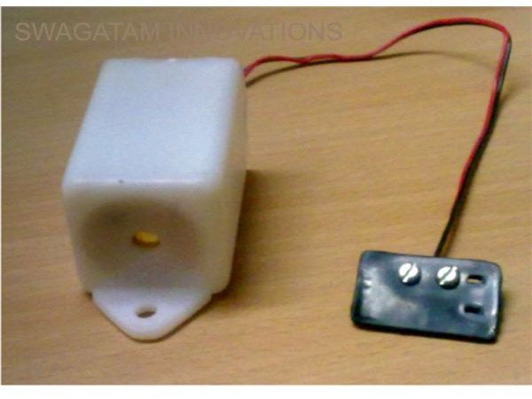
For the rain sensor circuit, the sensor part is easily built by fixing two 1/8 × 1/4 brass screws over a small piece of plastic at about 5 mm apart.
Connect the sensor to the circuit using flexible wires. The sensor needs to be placed outside the house, so dimension the wire lengths accordingly.
Similarly, for the light sensor circuit, configure and dimension the LDR connections as explained above, only if an extension of the LDR position is felt necessary, otherwise it may be fitted externally over the box itself.
Enclose the circuit in a suitable plastic box, with built in battery or the power supply, appropriately allowing the sensor wires to move out of the box.
The alarm circuits using 555 timer applications presented here are just a few to mention and hopefully you may get to read many more of them in my forthcoming articles.


