The simple 555 circuits discussed in this article include complete explanations using illustrations of a few easy to build circuits like a 555 electrical pulse generator and a voltage monitor. Read and enjoy building them.
IC 555 Configurations
We all know how versatile the IC 555 is regarding its wide range of applications. Basically the IC 555 can be operated in two most commonly used modes: monostable and astable multivibrator.
In the monostable mode the output at pin 3 of the IC goes high in response to an external applied trigger at its pin 2. The output holds this position for a time period determined by the values of its timing components consisting of a resistor and a capacitor.
The best example of this mode of operation of the IC can be studied in one of my previous article on a frequency meter . But the most common application of this mode of operation is in a 555 timer circuit, where the IC is used to switch ON a load at its output for the set period of time after which it is automatically switched OFF.
In the astable mode configuration the IC continuously produces pulses at its output. These pulses are normally square waves and its frequency can be adjusted again by varying the timing components comprising of a resistor and a capacitor. Let’s study regarding few simple 555 circuits.
Build These Simple 555 Circuits
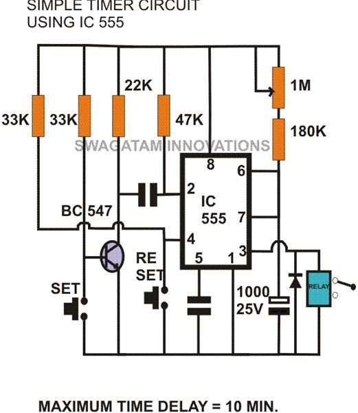
Simple 555 timer circuit: As shown in the figure the IC 555 is configured as a monostable mutivibrator. On pressing the switch S1, a momentary logic high appears at pin 2 of the IC and its output at pin 3 goes high switching ON the relay and the load connected to the relay contacts. The output will sustain the position till its timing capacitor C1 gets fully discharged through the variable resistor VR1. The value of this resistor may be varied to get the desirable time delays. The delay may be calculated using the below given formula:
T = 1.1 × (VR1 + R1) × C1
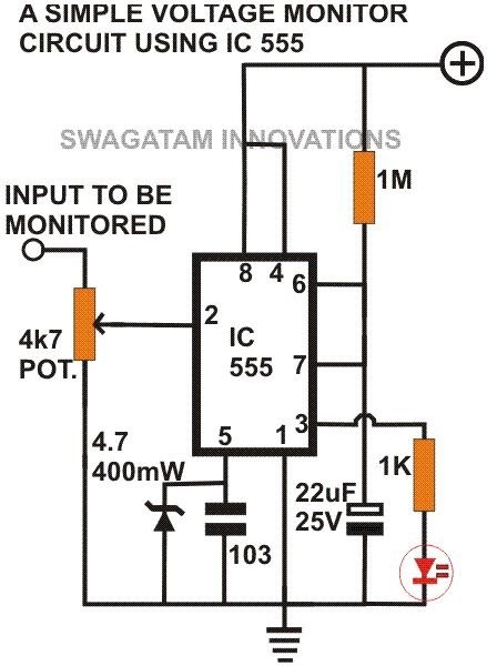
Simple voltage monitor: Another important use of IC 555 in the monostable mode is in the form of a voltage monitor. Here the voltage to be monitored can be set by the preset P1. For example if it is required to monitor a voltage level of 9, the preset may be adjusted accordingly. Now if voltage at pin 2 falls below 9 volts, the output will immediately go high giving a visual or an audible indication or can switch ON a relay to implement the desired safety measure. Similarly it can be used to monitor and sense a high voltage exceeding the set level.
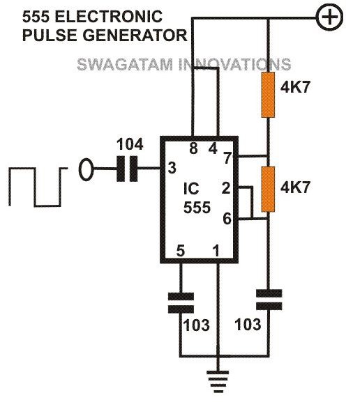
Simple 555 electrical pulse generator: Referring to the circuit diagram we can see that in an astable mode the IC oscillates continuously to produce a string of electrical pulses. These pulses are normally in the form of a square wave. Here no external trigger is required and the circuit starts to oscillate immediately on receiving the supply voltage. Its frequency can be altered by changing the value of either the capacitor C1 or the POT VR1. By sufficiently lowering the frequency and by connecting an LED at its output pin, the circuit may be used as a simple 555 led flasher. By increasing the frequency to a relatively higher level, the circuit may be used to drive a speaker or a buzzer to produce an audio tone.
The above mentioned 555 circuits are quite simple in design; hopefully you will enjoy building these circuits and see them actually working. If you need any help feel free to add a comment (comments need moderation, and may take time to appear).
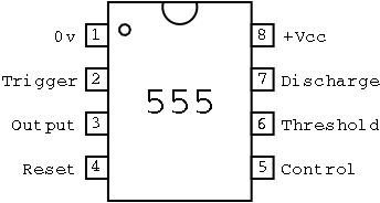
Pin-out Image Credit: https://pfnicholls.com/electronics/555_pinout.png


