An electronic gate is a combination of switches that are microscopic in size and whose function is to receive one or more inputs resulting in a single output. All digital circuits consist of electronic gates, as they are critical to a computer in decision making.
Basic Electronic Logic
When we talk about electronic logic, voltage and current represent a logic level. To achieve the required output voltage, each logic gate requires some input power to sink and source the currents. “Diode Logic” is the simplest form of electronic logic. In order to construct a logic system, transistors, relays, or vacuum tubes can be used. Relays were used the first time for design of electronic circuits . They were inexpensive but slow. This gave way to vacuum tubes. Vacuum tubes were faster than relays but they generated a lot of heat and were not very reliable. Then the first semi-conductor logic family was introduced called as “Resistor-Transistor logic.” Vacuum tubes were no comparison against this family. Resistor-Transistor logic, Diode-Transistor logic and Transistor-Transistor logic are the families of logic gates that were introduced to perform complex logic functions. The CMOS family was introduced afterwards and was meant for small scale logic. On the other hand, electronic gates are much more advanced, faster, and consume less power than other relay and switch equivalents. There is also a semi-conductor logic gate, which acts as a voltage gain amplifier.
Electronic Gates
The working of a computer depends on the electrical flow where 0 represents a low voltage current and 1 represents a high voltage current. The purpose of designing of electronic circuits is to control these negative and positive pulses into a meaningful logic. Electronic or logic gates are the building block of a digital circuit. There are three basic electronic gates by which a digital system can be constructed. These gates are:
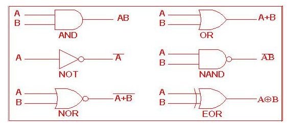
OR Gate
The OR gate is an electronic gate that gives a high output when one or more inputs are high. The symbol used to represent an OR operation is “+.”
AND Gate
The AND gate is an electronic gate the gives a high output when all of the inputs are high. The symbol used to represent an AND operation is “.”
NOT Gate
The NOT gate is an electronic gate that inverts the given input. It is also known as ‘Inverter’. For example, if the input to a NOT gate is B then the output is known as “NOT B.”
There are other gates that can be built using the basic electronic gates. These gates are explained below:
NAND Gate
NAND gate is the combination of AND gate and NOT gate. The input is received from the AND gate and after the output is produced, it inverts the output by using it as an input in NOT gate.
NOR Gate
NOR gate is the combination of OR gate and NOT gate. The input is received from the OR gate then the output is inverted by the not gate and the final output is the output of NOR gate.
XOR Gate
XOR gate is also known as “Exclusive OR ” gate. XOR gates are unique in the sense that they produce a high output when they receive both high and low inputs. If the inputs are all low or high then the output is low.
Applications
Gates are essential for the function of a computer system. It gives system the ability to perform complex computations in a very short period of time. These gates can also be put together to make half-adders and full-adders , which are capable of performing millions of calculations in seconds. Logic gates are also used in other circuits, such as flip-flops, in order to store information and act as memory. Random Access Memory (RAM) consists of a number of flip-flops . Electronic gates make sure that the data is traveling in the right direction within a computer system. Every digital product (computer, mobile, calculator, digital watches etc.) contains electronic gates. Logic gates provide the users with many solutions and options to many problems which may appear impossible to solve at first. These gates can be used in every kind of situation such as comparison of frequencies while developing filters in communication systems or in mechanical systems as well when choppers and inverters are being used to compare the input and output currents in order to calculate the modulating indexes.
References
What is Logic Gate?, https://whatis.techtarget.com/definition/0,,sid9_gci213512,00.html
Basic Logic Gates, https://www.ee.surrey.ac.uk/Projects/Labview/gatesfunc/index.html
Introduction to logic Gates, https://isweb.redwoods.cc.ca.us/instruct/calderwoodd/diglogic/


