You know that logic gates are used to make logical decisions using electronic circuitry. Just read about three such gates here namely OR, XOR and NOR gates and how much truth they speak.
OR Gate
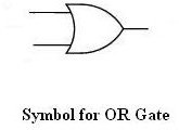
A logic gate has one or more inputs and one output. An OR gate as shown in the figure below (we have taken a two input OR gate for purposes of simplicity but this discussion applies to OR gates with more inputs as well) consists of two inputs and the output. The output depends on the input as follows
If both inputs are 0 or False, the output is 0 or False
If one of the inputs is 1 or True, the ouput is 1 or True
If both inputs are 1, the output is 1 or True
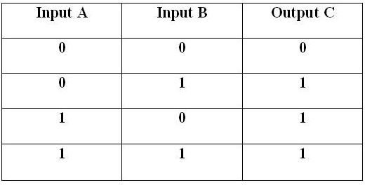
This can be expressed in the form of a truth table which is shown along with the symbol of the OR gate in the diagrams below
The table is self explanatory and A and B are two inputs which give rise to output C and there are four difference scenarios.
OR Gate - Symbol & Truth Table
XOR Gate
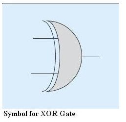
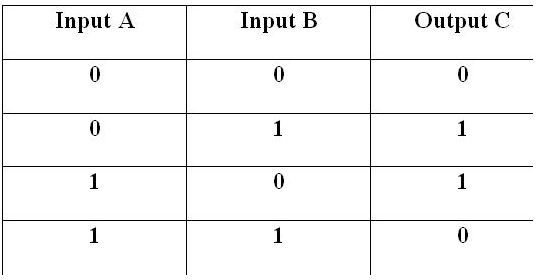
An XOR is known as exclusive-OR gate and is almost similar to an OR gate with the only difference that when both the inputs are 1 or True, the output is 0 or False, unlike an OR gate. Hence the truth table for the XOR gate is shown as follows and the symbol for it can be seen in figure below along with its truth table
XOR Gate - Symbol & Truth Table
NOR Gate
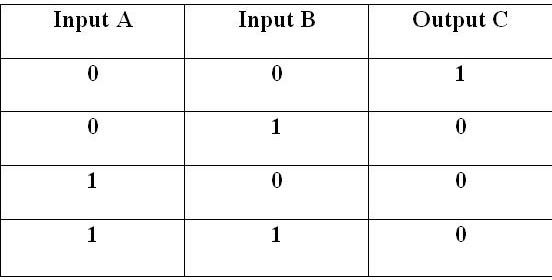
True to its name a NOR gate only produces a True output when neither input A, nor the input B is True but only and only when both inputs are false, hence the name NOR. The symbol and truth table of the NOR gate is as follows
NOR Gate - Symbol & Truth Table

The Actual Gates
You might be wondering as to how these gates are actually implemented in the electronic circuitry. I will not go into the exact details of these but just to give you a rough idea the actual logic gates are made out of electronic components such as diodes, transistors and integrated circuits. We will take the very simple example of a two input OR gate to explain this in more detail. Look at the figure below and see that how two diodes D1 and D2 are connected in parallel across the output C. when a sufficient voltage is applied across either any one or both of the diodes (which represents the state of 1 or True in Boolean equivalence) the diodes become forward biased and start to conduct current which causes output to appear at the other end. When the diodes are not forward biased, the output is 0 or False, hence it emulates the OR gate functions.


