Although a bit elaborate, the proposed design of a musical doorbell circuit provides some useful features like a built-in timer and a pleasing, replaceable audible note. Moreover, unlike conventional units, the present design is highly reliable and permanent in its operation.
In one of my previous articles I discussed the [wiring procedure for door bells](/tools/How to Build a Simple Musical Door Bell); here we will learn how to build a door bell, or rather a musical door bell. Although wiring a door bell involves purely electrical knowledge, working with the present theory will require some basic knowledge of electronics.
Door bells are perhaps among the most commonly and cheaply available electrical device available in the market, and there are hundreds of varieties to choose from. However with many companies joining the fray, the competition has become fierce, due to which the overall quality of such items has deteriorated with time. Initially these gadgets seem to work very fine, but pretty soon they just stop working and call for a replacement. However building one of these interesting musical devices all by yourself can be real fun and also you get the advantage of customizing the gadget as per your preferences.
Let’s move ahead and learn more about the working principle of this proposed circuit.
Circuit Stages
The schematic diagram alongside shows a straightforward design of an electronic musical doorbell basically comprising three important stages:
Timer: As the name suggests, the function of this stage is to produce a certain time delay for keeping the music or the output audible even after the call bell button is released and the power to the circuit is switched OFF. The configuration is basically a mono-stable multi vibrator which holds the output and the relay in an energized position for a time period determined by the value of C2 and the setting of VR1.
Audio/Music Generator: Here’s where the popular chip UM 66, which contains an embedded piece of music information in it, becomes the primary part. This device looks pretty similar to an ordinary transistor, but is actually an Integrated Circuit performing the outstanding function of generating complex music codes at its output lead that just need to be amplified for listening.
Primarily the IC consists of three leads, which may be identified as follows:
Keeping the printed side towards us, the left lead is the ground or the negative; the center is the positive supply input while the right lead is used to receive the audio frequency. The IC operates specifically at 3 volts, which needs to be regulated in case the supply voltage used is higher. In the proposed circuit, since the voltage is 12 volts, a circuit consisting of R4 and Z1 is utilized for the required stabilization and provides a stable 3 volts to the IC. The output from the IC is fed to T3 via R5 for the necessary amplification directly over a small loudspeaker.
Power Switching: This configuration consists of a feed back loop connecting the output to the input mains supply via the relay contacts. The stage is used to hold the mains supply once the bell switch S1 is released.
The following section reveals the practical functioning of the above stages once built and installed.
Circuit Functioning
To initiate the bell, P1 is switched ON momentarily which provides the actuating mains power to the circuit monostable by by-passing the relay contacts. The monostable instantly triggers charging C2, switching T1/T2 and the relay.
The N/O contacts instantly latch up so that now the power is bridged and sustained through these contacts even after the bell-switch is released. IC1 also immediately starts generating the audio note which gets amplified through the speaker and constitutes the bell sound or alarm.
As already discussed the music continues until C2 is completely discharged through VR1 and T1 when finally the monostable breaks the relay latch and the power. The music is then switched OFF and the circuit returns to its initial state.
Important Features
By replacing the transformer by batteries, the circuit can be easily made battery operated.
VR1 can be used to adjust the length of time for which the music remains audible once the bell switch is released.
The IC UM 66 lead positions can be simply replaced by other COBs to get a variety of music output options.
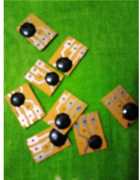
The image below shows how COBs look, the coded chip is safely embeded under the black epoxy droplet and its connecting leads are appropriately terminated through three discrete copper tracks. The terminals are identified by the markings etched over the board, just beside the relevant leads.
To learn more about COBs please refer the article on “how to make a musical greeting card”.
Idea Developed by Swagatam.
Parts List
R1, R2, R3, R4, R5 = 1K,
VR1 = 100K Pot linear,
C1, C2 = 470uF/25V,
D1, D2 = 1N4007,
Z1 = Zener Diode, 3V/400mW,
T1, T3 = 8550,
T2 = BC557B,
IC1 = UM 66 or equivalent COB,
Relay = 12 Volt, 400 Ohms,
Speaker = 8 Ohms, 2.5”,
Transformer = 12V/500mA, (Input 230V or 120V),
S1 = Switch Bell Push
References
-
Author’s own experience.
Images - By the author.


