Want to surprise your dear one by sending a self made musical greeting card? A little knowledge of electronics and the simple instructions provided here is all that you need to make a greeting card “sing” every time it’s opened.
Parts List
You will require the following parts to make your own musical greeting card:
A readymade printed greeting card having a rigid body – 1 no.
A musical IC, also called COB, select one which may have one of your favorite embedded melodies, like “Silent Night,” “Home Sweet Home,” “We Wish You a Merry Christmas,” “Titanic,” etc.
Transistor 8050 and BC 557 = 1 each
Piezo Buzzer = I each
Resistor 2K2 = 1 each
LDR = Producing less than 10K resistance under normal house interior lights
Button Cell = 3 Volts
A bundle of flexible wire = 7/36
Thin opaque plastic or cardboard sheet, cut exactly to the size of the procured greeting card
Good quality glue for sticking plastic to paper
How to make your Musical Greeting Card
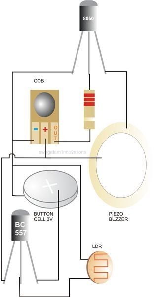
As illustrated in the diagram alongside, wire up all the involved components (except the cell) by interconnecting them through small pieces of the given flexible wire. The connections to the relevant points should be done by soldering the stripped ends of the wires.
After this, place the above wired mesh over the left hand inner blank side of the greeting card. Adjust each component so that they lie as flat as possible with the card background.
Glue each component with the card on which it’s placed and let it dry.
Once the entire assembly dries and is firmly fixed, you may attach the 3 V cell to it. Don’t worry if it starts “singing,” as it will remain on only for the time the card remains open (while you’re doing the finishing part and the LDR remains exposed.)
Finally size up the procured thin plastic sheet or a cardboard and glue it over the electronic assembly so that all the “machinery” is hidden. Make sure that you make a small opening above the flap for the LDR to enable it to “see” light whenever the greeting card is opened.
Circuit Description
The circuit is actually quite self-explanatory, does not require elaborate explanation, and can be easily understood from the following points:
A COB having an embedded piece of information in it (here in the form of music) forms the heart of the circuit. It generally has three terminals, which can be easily identified from the markings made over its PCB track layouts. The center one will be the positive, the left one the negative, and the right side track the output.
COBs normally work strictly at 3 volts DC and require a resistor/zener stabilizer circuit if the supply voltage used is higher. However since here we are using a 3 volt cell and the volume requirement is quite negligible, the COB is driven directly with the cell supply without using any voltage regulating components.
A single general purpose transistor 8050 is enough to convert the tiny musical frequencies into much stronger audible music signals through the piezo element.
Another general purpose transistor BC 557 in conjunction with an LDR forms a light sensitive power supply circuit. As soon as light falls over the LDR, its resistance falls and it triggers the transistors so that it can conduct and power the audio section. This happens when somebody opens the greeting card and on doing so allows the ambient light to fall over the LDR positioned exactly for that purpose.
References
-
Author’s own experience.
Image - Drawn by the author.


