The IC 4060 has a built in oscillator, the frequency of which can be adjusted simply by altering the values of an external resistor, or a capacitor. A comprehensive discussion regarding the pin outs of 4060 oscillator is included herein.
Introduction
We have been studying a lot about microprocessors and have taken a look at the 8085 architecture . We also learnt about several interesting and easy circuits to build on your own such as RF detector . In this article we will focus our attention on the IC 4060 oscillator and learn about its working principle.
The IC 4060 is highly versatile and has unlimited applications in electronic circuits. It is basically a 14 stage binary ripple counter and consists of an internal oscillator. The IC requires just a couple of resistors and a capacitor connected externally to start the oscillator.
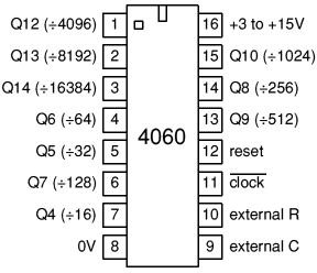
Its 16 pins are designated as follows:
- Pin 1 to 7 and 13 to 15 are the outputs of the IC.
- Positive supply is given to pin 16. Like all CMOS Ics it should be in between 5-15 volts.
- Pin 8 is to be connected to the ground.
- Pin 9, 10, and 11 are reserved for the external frequency determining components.
- Pin 12 is the reset pin.
How to Identify the Pin numbers?
Generally most ICs have a sunken circle just beside pin 1, otherwise it can be identified as follows:
-
Hold The IC with its printed surface facing towards you and the end with a semi circle notch pointing upwards.
-
In this position the pin beginning at the left of the notch is pin 1 and the pin ending at the right of the notch is pin 16.
How IC 4060 is Wired as an Oscillator?
The internal oscillator of the IC 4060 can be made to oscillate just by connecting a couple of resistors to pin10 and 11 and a capacitor to pin 9. The free ends of these components are all joined together. Reset pin 12 should be grounded. Resistor at pin 11 should be roughly 10 times that of resistor at pin 10.
The resistor at pin 10 or the capacitor can be made variable, if the frequency is to be varied, otherwise fixed values may be chosen.
After completing the above configuration, connect pin 16 and pin 8 to their respective supply terminals and switch ON the supply voltage. The internal oscillator of the IC should immediately start oscillating.
The frequency of each output will be the double of the previous one and is obtained in serial order through pin 3, 2, 1, 15, 13, 14, 6, 4, 5, and 7. Thus for example if the frequency at pin 3 is 1Hz, the frequency at pin 2 will be 2Hz, at pin 1 it will be 4 Hz ,at pin 15 it will be 8Hz and so on.
The oscillator can be stopped or reset by applying a logic 1 or a positive supply to pin 12 of the IC.
The oscillator can be latched after a set period by connecting the appropriate output to pin 11 through a diode.
Image courtesy: Cool Circuit Website


