A cross section view in Pro-E can be created in part as well as in drawing. This Pro Engineer tutorial will walk though the procedure for drawing a ProE Section View.
Like Unigraphics , Solid Edge and other 3D CAD packages, you can create the cross section view in ProE also. Pro-E cross section views can be created not only in Pro Engineer drawings, but also in part and assembly. Let’s say we need to create the cross section view of a hollow ball. Below are the procedural steps for drawing ProE section view:
Step-1
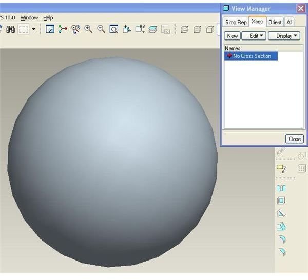
Create or open a hallow ball in ProE. Then go to V**iew>View manager** and you will get the view manger window. Now go to the Xsec tab of the view manager window. It will look like below:
Step-2
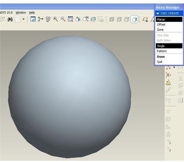
Click on the “New” button in the view manager dialog box to create a new cross section. You will see a cross section named Xsec0001 added. Press “Enter” and you will get the following options for creating the section view:
Step-3
For creating planer section view leave the “planer” and “single” highlighted and click on the “Done” button. You will get the following options for selecting or creating the datum plane:
Step-4
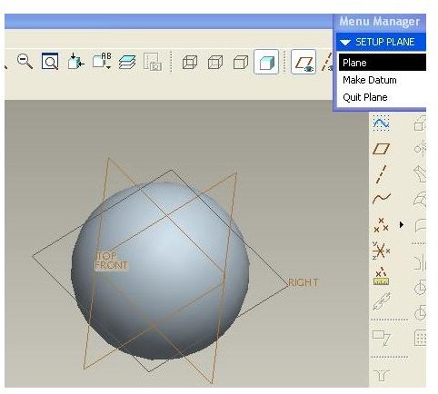
If you already have the datum plane through which you need to create the cross section view then click the “plane” option and it will direct you to select the datum plane. In case you have not created the datum plane yet, then you can create a datum plane here by clicking the “Make datum” option.
Step-5
Once you have selected the required datum plane, you will complete the cross section creation process and will return back to the view manager dialog box. Double click on the “Xsec0001” to activate the section view.
Step-6
In case you want the cross section view to be visible in the drawing, right click any of the view in the Pro-E drawing of the ball and click properties, then go Sections then click on “2D cross section”. Now you have to add the Xsec0001, you already created, by clicking “+” just below the 2D cross section. Click apply and OK. You can see the cross section view in that view.
Conclusion
Drawing ProE section view is important because cross section view gives the inner details of any part or assembly. For example you have internal welding and you want to see the welding size . Pro-E gives you the privilege of drawing cross section view in Pro Engineer assembly, parts and drawing.
Related Readings
Some Important Tips to Speed up your Modeling in Pro-engineer : When you are working with some real time design project of pro engineer, you will always be failing short of time; always you will be having delivery schedule pressure. We will discuss some of the pro engineer modeling tips which will help you work efficiently with pro engineer.
How to Create and Use Family Tables in Pro Engineer : Pro engineer is having a very effective method to create database of any numbers of similar parts/assembly with modeling only one of them. The method is called family table. We will discuss about family table in this article.


