CAD applications like ProE and Solidworks as well as many others have extensive complex functions such as sweeps and surface functions that can be used to create objects such as auto body parts and other thin surfaces. Another method of creating these complex models is to use simple features.
Complex Models made Simple
The advantage of using simple functions as opposed to complex surfacing functions in various 3D modeling applications is that the average user who is not well versed in surfacing can create complex parts. The disadvantage though is that when attempting to modify the design you will most likely run into errors. If you are confident with specific dimensions and are comfortable dealing with fixing chamfer and rounds errors, then this may be a possible path that will open up the world for you to design complex surfaces using simple tools.
This tutorial will give tips and ideas on the order of operation that should be followed in order to minimize errors. The final goal is to design a custom auto body for a go cart that is 3000 mm x 1500 mm.
Step 1
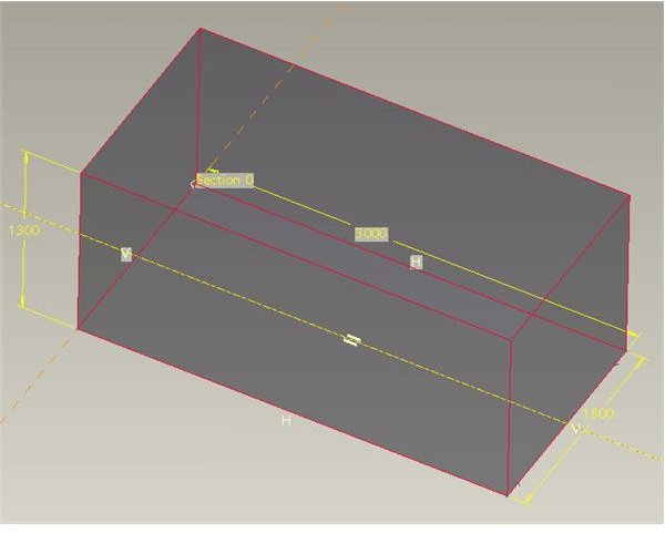
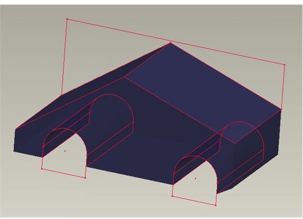
Create a square based on the body size that you intend to create. In this case, I’ve extruded a simple block that is 3000 mm x 1500 mm x 1300 mm tall. You should minimize using any rounds or circular cuts unless absolutely necessary, but since this is an auto body, a lot of rounds and curves are necessary. The simple tools that are used in this step are chamfers and extrudes. Also note that I’ve extruded the block so that one of the datum planes runs through the center of the block. This comes in handy for mirroring features which we will get to in the future. Setting up this block properly will help make life much easier as the model becomes more complex.
Images
Step 2
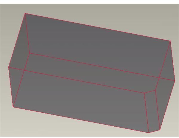
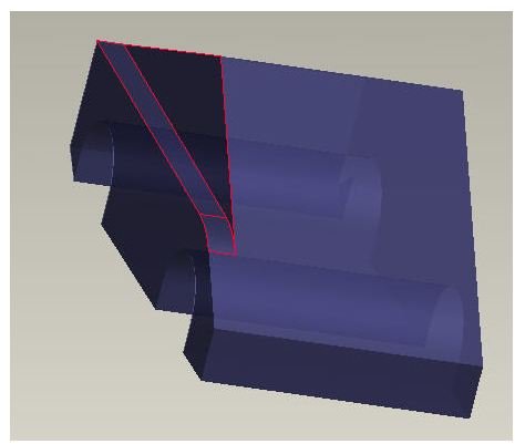
Now start adding in chamfers and extrudes. The first item I added in the model was a chamfer located at the rear bottom of the car. This helped me to orient the model.
Next I performed several extrudes. These gave me the side profile of the car including the cutouts for the wheels and also the angle for the windshield / hood and the rear of the car. My aim was to make it sporty and since I am a big fan of Ferrari and Lamborghini, I am going to try to go for that muscle car look.
Images
Step 3
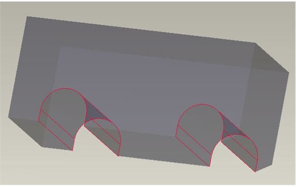
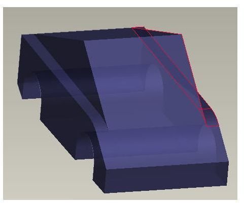
Now let’s start working on the profile of the car looking at it from the front.
I added in a cut on the Right Hand (RH) side of the car. This is a simple extrude function again with a nice circle added above the front wheel. Make sure you spend some time and really pay attention to the detail when drawing out the extrudes. Focus on following maintaining tangencies and you result will be a smooth flowing design that will be aesthetically pleasing. Sharp cuts may cause you issues and problems in the future when trying to round them out.
Use the mirror function to add symmetry to your model on the Left Hand (LH) Side of the car. This is where using the default plane in the center of the model comes in handy. If you did not set the default plane in the center of your model, you can easily create a plane in the center of the car and use this as well. Make sure you move this plane to the top of your model tree as you will be referring to this plane often as there are a lot of mirrored features.
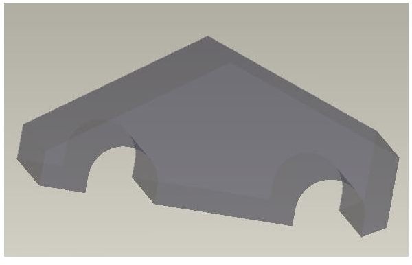
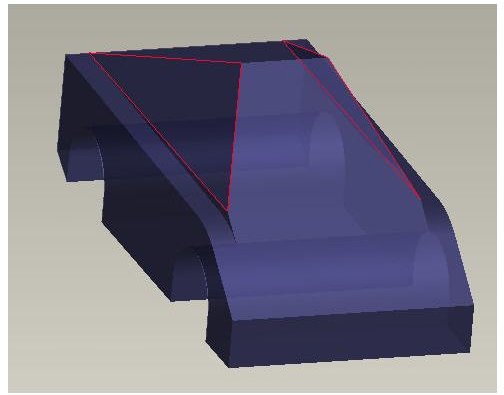
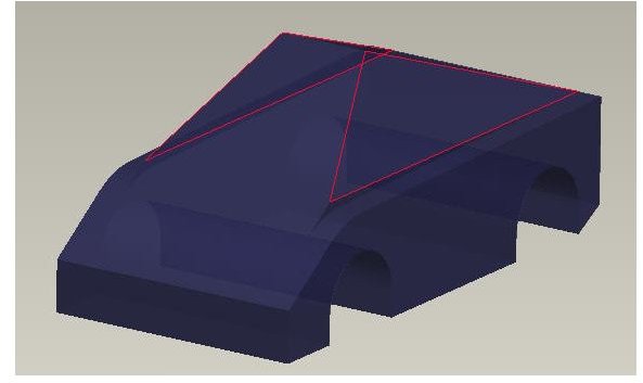
After the mirrored feature, I added in the angle for the top part of the car. These angles really make the car look aesthetically pleasing and also serve the function to reduce additional frontal profile surface area.
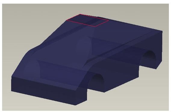
Finally a chamfer on the top of the car to make it flat and with only a few features, we have a pretty nice looking sketch of an auto body. The next tutorial article will get into adding in more features to make the car look like a muscle car and also will get into shelling out the model.
Images
Save
This is an ideal place to stop and back up the model. The next steps will start adding in cuts and rounds which could potentially cause issues. If you run into a problem, it will be easy to just start from this model and continue again without having to backtrack and try to fix the complex rounds errors you have created.
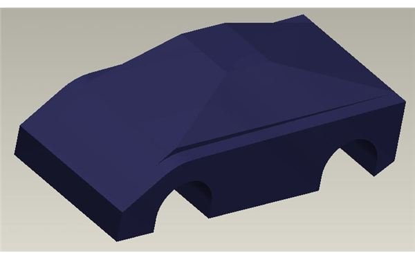
Completed Model So Far
This post is part of the series: Creating Complex Models Using Simple Modeling Features
Softwares like ProE and Solidworks as well as many others have extensive complex functions such as sweeps and surface functions that can be used to create objects such as auto body parts and other thin surfaces. Another method of creating these complex models is to use simple features.


