This Unigraphics NX6 tutorial will talk about the important sketch tool available in sketcher mode where you can create a 2D sketch of a 3D UG model.
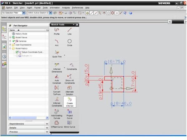
Once you enter sketcher mode of UG NX6 you will see a GUI like this (click on the image to enlarge).
Notice the “Sketch Tools” panel, you see there are many icons (like line, circle etc.) over there. Most important of them are:
- Line: By clicking this icon you will be able to draw line entities. You can either click on the screen or enter the point coordinates, or specify the distance between two points to draw a line in Unigraphics sketcher mode.
- Circle: This UG sketch tool is for creating circles. You have the option of either specifying a center and diameter or three points on the perimeter to draw a circle.
- Arc: For creating and arc in Unigraphics sketcher mode, click this icon. Like circle, you have two options: specifying centre and diameter or specifying three points.
- Profile: For fast sketching in UG, use this tool. This is a combination of line and arc. You don’t need to click different icons in between.
- Trim/Extend: These icons are used for trimming or extending lines or curves.
- Dimensions: You have separate icons for different types of dimensions. Click suitable types of dimension icons. For example, you may go for horizontal dimension, vertical dimension, angular dimensions, radial dimension, etc.
Alternatively, you can click “Inferred Dimension” and select any entity; UG will decide a dimension type depends upon the entity geometry. For example, if you select an arc, UG will give Radial dimension and if you select line it will give parallel or horizontal or vertical dimension.
- Constraints: Apart from dimensions you need to give geometric constraints to make any UG sketch fully constrained. Various geometric constraints are available by this icon. The procedure is: Click on entity/entities then click on the “Constraints” icon. Unigraphics will show all the possible geometric constraints between the selected entities. Select any one of them. For example if you hit “constraints icon” and select two sides of a polygon, you will get geometric constraints like: parallel, equal, perpendicular, etc.
- Inferred Constraints: If you want Unigraphics to suggest geometric constraints while creating the entities then click the “Inferred constraints” icon and set what all the constraints you need. Next time while creating entities you will see the possible constraints adding up automatically.
Conclusion
The Unigraphics NX6 has an important and easy-to-use sketch tool. Profile, Inferred dimensions, and Inferred constraints are some of the functions available with tho UG NX6 sketch tool that will help you speed up your sketching.
Related Reading
Manage Your RSS Feeds in AutoCAD 2009 - You are net savvy and you love reading lots of RSS feeds. Now with AutoCAD 2009 you can monitor and read the latest updates of your favorite feeds while doing your design work, with no need to minimize AutoCAD and start any other RSS reader.
Creating Reference Planes in Solid Edge - Effective use of the reference plane creation tool in Solid Edge is the key of your capability to handle complex 3D CAD models. There are many options available in Solid Edge for reference plane creation. Here we help you understand and practice the concepts behind each option.
An Introduction to Solid Edge - User-Friendly 3D CAD Software - Like other 3D CAD software Solid Edge is also used extensively for 3D CAD modeling. It is easy to learn and use. Let’s give it a closer look.


