Effective use of the reference plane creation tool in Solid Edge is the key of your capability to handle complex 3D CAD models. There are many options available in Solid Edge for reference plane creation. Here we help you understand and practice the concepts behind each option.
There are many ways you can use to create a reference plane in Solid Edge. It is not important to choose just any one method, but it is important to choose the correct one. Else, you will be spending more time in 3D CAD modeling than you have to.
What is a reference plane?
While working in 3D CAD software (like Solid Edge) you will be dealing with 3D space. You will sometimes be required to draw a 2D sketch in 3D space. These sketching planes are called reference planes in Solid Edge. Most other 3D CAD packages use the term “Datum Plane” instead of “Reference Plane.” Though the primary function of a reference plane is acting as a sketching plane, it has other functions as well. A reference plane, for example, could be used as a reference in assembly as well as a part.
Types of reference planes
There are three types of reference planes in Solid Edge:
- Base Reference Planes: When you open a new part or assembly file in Solid Edge, you will see three mutually perpendicular planes at origin. These are called base reference planes. By right clicking you can hide or unhide any or all of the base references.
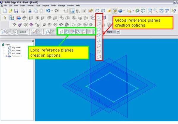
- Global Reference Planes: While modeling in Solid Edge, you may require some additional reference planes apart from the existing base reference planes. You can create those additional reference planes in two ways: creating the reference planes while creating the feature itself and creating reference planes separately. When you create the additional reference planes separately those reference planes are called global reference planes.
- Local Reference Planes: If you create the additional reference planes while creating the features itself, then the reference planes are called local reference planes.
How to create reference planes
Base reference planes cannot be deleted or created, but they can be either global or local reference planes. Moreover, options available for creating global reference planes or local reference planes are same. We will discuss the available options for creating global as well as local reference planes with respect to the below attached snap (Click on the snap to enlarge):
To create global reference planes you have to click the respective reference plane icons from the feature tool bar, and for creating local reference planes you have to click the respective reference plane icon from the SmartStep ribbon . The rest of the procedure is the same for global as well as local reference plane creation.
-
Coincident Plane: You can create a plane coinciding with another plane or face by clicking the “Coincident plane” icon either from the feature tool bar or from the SmartStep ribbon. Select on the plane or face where you want the new reference plane to coincide.
-
Parallel Plane: You can create a reference plane parallel to an existing plane or surface by clicking the “Parallel plane” icon. You have to select the plane or face of which you want your new reference plane to be parallel. Also, you have to specify the dimension between the two planes.
-
Angled Plane: You can create a plane inclined with some face or plane by this option. You have to select the face and edge to define the angle.
-
Coincident Plane by Axis: This is similar to the “Coincident plane” but you can orient the resultant plane here.
-
Plane Normal to a Curve: You need to have a curve first. Select the curve as input here, and you will see a reference plane created. You can drag the reference plane by mouse to place it at suitable position.
- Plane by Three Points: Select any three points and you will get a plane joining those points here.
Conclusion
Reference planes creation is important for modeling efficiently in Solid Edge. Base reference planes cannot be created or deleted. Local and global reference planes can be created by various options available in Solid Edge.
Related Reading
Solid Edge: User-friendly 3D CAD Software - Review - Like other 3D CAD software, Solid Edge is also used extensively for 3D CAD modeling. It is easy to learn and use. Let’s give it a closer look.
Creating Basic Features in Solid Edge: Protrusions - Protrusion is one of the most used features, not only in Solid Edge, but in all 3D CAD packages. Here we’ll look at how Solid Edges “SmartStep” ribbon bar makes creating a protrusion easy, logical, and quick.


