Following the SW2008 overview, sketch relations, extrude series, and revolved protrusion guide, this article presents the tutorial on making swept extrusions in the SolidWorks program.
Introduction
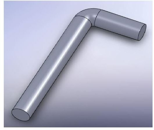
So, you have mastered the sketch construction, and the extrude process in the new SolidWorks 2008. You have also experimented with revolved features, improving your SW experience. But sometimes there are parts and details that cannot be just “extruded” or “revolved”. What if your part looks like this:
The need
Revolved protrusion is not an option here, since the is no axis to revolve about. You could try to construct is using a rectangular L, and after that – to round the corners and edges. I must note, this may result in similar part – but prepare to face many problems. Also, it would be problematic to edit the part afterwards – as there would be no connection between the rectangle and the round radius. Using the “swept protrusion” option, we can create the part with 1 step – though a complex one.
“Sweep” feature (called “Swept Boss/Base” in Solid Works 2008) means that your part has a certain constant cross-section that can be “moved” along certain pass. This is exactly the case with the above detail – the constant circle cross-section that is “moved” - swept(!) – along the “L-type” path.
Swept Boss/Base
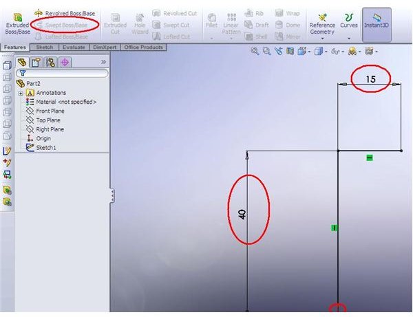
So, let’s get familiar with the Sweep Protrusion. As you can see, the feature is not available in the new part. That’s because 2 sketches are needed to define it.
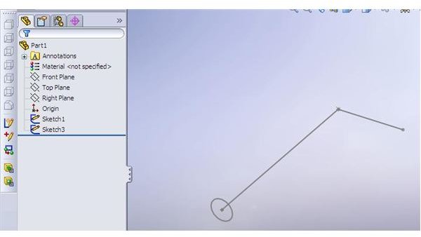
Click on any of the principle planes, and draw a profile. I would recommend constructing a “path” profile first (the “L” along which the circle would be swept). It is also very important to completely define the sketch (as you probably learned in the “sketch relations” series). Dimension the sketch and make sure it is completely defined. It is also advisable to connect the path start to the point of origin.
3D view
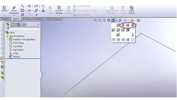
After you have constructed the first sketch – another sketch is needed – the “profile” sketch. It has to be constructed in plane that is orthogonal to your plane. Go to Isometric view to be sure you are picking the right plane for the second sketch.
Profile sketch
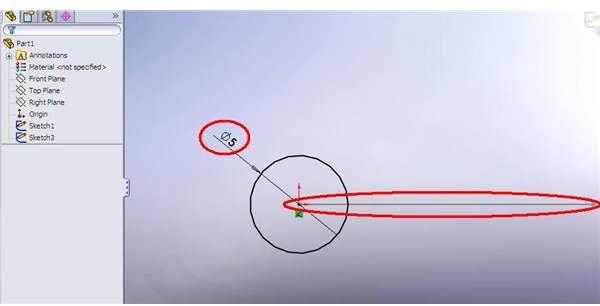
Use point of origin as a reference (that’s why we have connected our first sketch to it) and construct a circle. Dimension it to “fully defined” and exit the sketch. Now we have 2 sketches and we are ready to construct our “swept part”. How to do that? Read in the next article!
This post is part of the series: Creating Swept Protrution in SW2008
Sweepig a profile along a path can save you quite a lot of time when you are dealing with complex parts in Solidworks. Learn to create a Swept protrusion with this series - that oresents the overview of the Sweep Boss/Base feature.


