Following the SW2008 overview, sketch and extrude series, and revolved protrusion process, you are now dealing with “Swept Protrusion”. This article continues the tutorial on making swept extrusions in the SolidWorks program.
Introduction
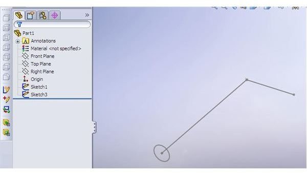
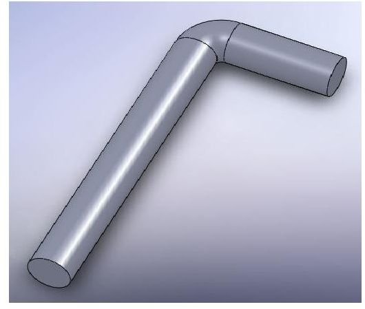
In the first article of the series, we have recognized the need of using more advanced tools than the simple extrude and revolved features. One of such features is Swept Protrusion. This construction option is defined by 2 sketches – a cross-section that is “dragged” along certain path. Remember, our part-to-be-modeled looks like this:
The sketches
In Part I of the series we have constructed the 2 sketches that define the Sweep process:
Now, go to “Features” tab of the menu and choose the Sweep Boss/Base option. A screen will appear, asking you to define various feature options:
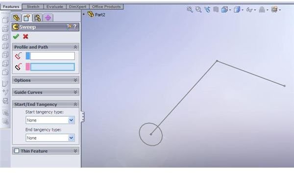
Sweep Boss/Base
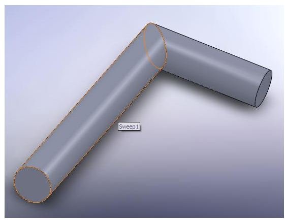
Choose the circle sketch (that we have created second) as cross-section as the “L” profile as a path. The preview of the part will appear. Now, let’s check other sweep protrusion options:
Options
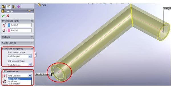
The “Thin-wall” feature should be already familiar to you. It allows the construction of “thin-walled” contour, using our profile as a midplane, inner or outer surface. The should be defined. In our case (if we wish to construct a pipe rather than bended round bar) – it maybe advisable to use this option.
The “Start/End Tangency” allows then user to define (if the profile and path planes are not orthogonal) the orientation of the cross-section profile at both ends of the path profile. It can be set orthogonal to the path profile even if the sketches are not.
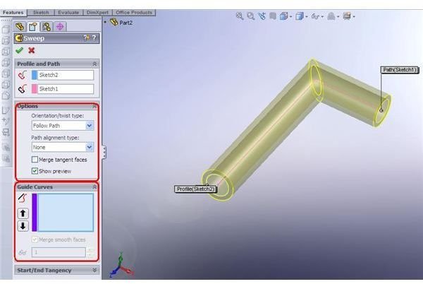
The “Guide Curves” are used to define the “twisting” of the cross-section profile. It is a rather advanced option that will be dealt more in-depth in the “Lofted” protrusion overview.
The “Options” include several other options.
- The possibility of “preview”. If this option is on and you do not see a preview – probably your part cannot be constructed with the defined parameters.
- The merge tangent faces allows smoother “sweep” of the profile.
- The orientation/twist part option is used to define the cross-section profile behavior. When the path profile is more complex than our “L”, there may be several options that will produce different models. When you choose “Follow path” – you will need to set alignment type, defining how does the cross-section “behave” when faces are created.
In general, those options are pretty advanced, and would be better explained in the following articles. What you need to do now is to press the green “V” – and your part is constructed!
Images
More to come
But wait a minute! Do you notice the difference between the 2 parts above? Our part has “sharp” corner, instead of bend radius! Shouldn’t that be corrected? Of course! To do that we will edit the sketch and use “sketch fillet” – but that is another article!
This post is part of the series: Creating Swept Protrution in SW2008
Sweepig a profile along a path can save you quite a lot of time when you are dealing with complex parts in Solidworks. Learn to create a Swept protrusion with this series - that oresents the overview of the Sweep Boss/Base feature.


