A resistive load can be simply controlled by varying the applied voltage. But controlling inductive loads like an AC motor definitely isn’t that simple and can be done only through VFDs. Here we comprehensively discuss the purpose of a VFD and how a VFD works.
What’s the Purpose of VFD’s?
A VFD (Variable Frequency Drive), or rather a VVFD (Variable Voltage and Frequency Drive) is a precision electronic device specifically designed and used to control the speed of AC induction motors (single as well as three phase) without affecting the electric consumption, torque, impedance, magnetic flux, etc. of the motor. It is integrated to an operator interface for receiving the required speed control commands (using keypads). Why can’t VFDs be replaced by other straightforward means? The following discussion will provide the exact purpose of using VFDs to control AC motor speed.
The fundamental speed of any AC motor is inversely proportional to its number of stator poles and directly proportional to the supply voltage’s frequency. Therefore, to alter the speed of an AC motor, we need to either change the frequency or the number of stator poles. Since the number of stator poles for every motor is fixed, obviously we cannot change them. By varying the frequency of the supply voltage through some simpler means, the speed of the motor can be changed.
However, changing only the frequency at a constant voltage (120 or 230) causes the equivalent impedance of the motor to decrease, resulting in greater magnetic flux and causing the motor to start drawing dangerously huge currents. Therefore it becomes imperative that the supply voltage is also proportionately reduced along with the frequency at a particular fixed ratio. Failing to do this would cause the magnetic flux of the motor to saturate and the motor to become damaged. Varying the frequency and voltage proportionately also ensures a constant torque since the magnetic field in the air gaps is constant.
The purpose of a VFD is specifically intended to control the speed of an AC motor by strictly observing the above parameters. Here, the speed of the motor is varied by changing the magnitude of the input voltage as well the frequency at a constant ratio and thus the motor is able to maintain a constant torque even at lower speeds.
What’s Voltage to Frequency Ratio, and Why it is so Vital?
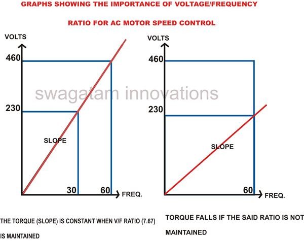
The basic characteristic of AC motors makes it imperative that the applied voltage and the frequency to it are always at a particular constant ratio. Referring to the adjoining graph (click to enlarge), let’s consider the example of an AC motor operating at 460V/60 Hz frequency for optimum performance (the slope indicates it and also the torque). Now, if the applied voltage is reduced to 230 volts, keeping the slope coincident to the original, we clearly see that the frequency required is 30 Hz. The second graph simply indicates how the slope or the torque of the motor falls in case the frequency is not changed and is kept at 60 Hz. Dividing 460 by 60 or 230 by 30 we easily find the required safe operating ratio for the AC motors which comes to about 7.67 volts per hertz.
This is exactly what the VFDs are designed to maintain and is the main purpose of a VFD.
Having said that, it will be also important to know that an AC motor speed cannot be varied beyond its specific base speed (rated name plate speed). Exceeding this limit will cause field weakening, a reduction in the torque, and a nonlinear or abrupt behavior of the motor.
As the above theory should have helped you understand the purpose of a VFD, the next page will explain the operating principle of a VFD.
How a VFD Works?
The electronic circuit in a VFD unit is discretely divided into three main stages, viz. an input converter (bridge rectifier stage), a DC Bus (filter stage), and an output inverter (using microcontrollers and IGBTs).
Let’s look at how each stage works.
-
Input Converter: This stage consists of high power diodes arranged in a regular bridge configuration. The AC mains applied here is rectified and converted into DC. But this DC is not free from the residual AC components and harmonics. It requires further filtering.
-
DC Bus: Here the rectified DC is stripped and filtered from the left-over harmonics and AC residues using inductors and capacitors. This stage helps in making the output to the motors totally ripple free and ideal for AC motors.
-
Inverter: As the name indicates, this stage converts the DC from the DC bus back to AC, but in a very special way that forms the heart or rather the brain of the circuit. It consists of sophisticated microcontroller ICs designed and programmed especially to change the output frequency along with the voltage proportionately and also create a three-phase output from a single phase input. This stage particularly makes VFDs very unique and most ideal for controlling AC motor speeds.
-
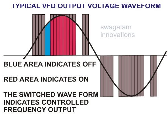
Output: The command from the above stage (microcontroller ICs) are sent to the output IGBTs (Insulated Gate Bipolar Transistors) which switch the voltage received from DC bus into narrow chopped steps (quite similar to the principle used in Dimmer Switches ). To do this the ICs employ PWM technology and convert the DC into quasi-sinusoidal waves. The longer the switching time of these waves, the higher is the voltage at the output to the motor and vice versa. This procedure is actually responsible for two important functions – to change the output voltage without any wastage of electricity and, very crucially, to change its frequency simultaneously at a particular given rate to keep the torque and the magnetic flux constant.
Briefly, a VFD has the following important features:
- Over-current protection, especially useful while controlling motors with high inertia.
- Constant torque ensures wider range of speed control, enabling an energy efficient control throughout the range.
- The VFD acts as a barrier in between all input voltage disturbances like harmonics, ripples, sags, surges, etc., and obstructs them from entering the motor.
References
If you need more information, you may find the following web pages helpful.
https://www.kilowattclassroom.com/Archive/VFDarticle.pdf
https://en.wikipedia.org/wiki/Variable-frequency_drive
https://www.ctiautomation.net/PDF/Articles/What-Is-A-VFD.pdf


