Power Factor Correction can be performed by passive or active circuits. The advances in semiconductor technology and the low price of control integrated circuits have made the use of active solutions for PFC more appropriate for a wide range of applications.
PF Defined
Power factor (PF) is defined as the ratio of the real power to the apparent power in an electrical system. The so-called real power is related to the effective energy that can be transformed into work in a certain interval of time. Since in alternating current (AC) circuits the instantaneous current and voltage vary continuously, the active power is calculated as the average value of power as a function of time over a complete AC cycle. The apparent power is simply the product of the RMS value of the current and the RMS value of the voltage of the circuit. It is a combination of active and reactive power. The reactive power is a function of the reactance of a circuit.
Electrical systems usually consist of some combination of resistive, inductive, and capacitive loads. Ideally, inductors and capacitors do not dissipate energy, but they store energy and return it back to the source. This back and forth energy flow places a heavier load on the utility. Inductive loads are mainly represented by transformers, motors, and coils, and consume (reactive) power by delaying the current in relation to the voltage waveform. Capacitive loads such as capacitor banks or buried cables generate reactive power where the voltage waveform phase is delayed in relation to the current waveform phase. The power factor is 1 if both current and voltage waveforms are sinusoidal and in phase.
Power Factor Correction
Low power factor (PF) causes power losses in the distribution system. Some procedures can keep the PF of an industrial electrical system at an acceptable level such as: (i) minimize operation of lightly loaded motors, (ii) operate equipment in their rated voltage and (iii) install capacitors to decrease reactive power in AC circuits. Some specific types of circuits can also be used to increase the PF of a system. Silicon controlled rectifier (SCR) or TRIACs are used in phase-controlled power supplies to control the phase of the input signal, which is filtered by an LC-type filter.
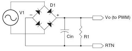
One of the most used PF correction circuits in today’s power supplies consists of a switched-mode boost converter placed between the input rectifier and the storage capacitor. An integrated circuit (IC) controls the converter in order to make the input current match the input voltage waveform. A typical switched-mode power supply (SMPS) without PF correction has a PF around 0.6. The low PF along with harmonics reduces the energy that can be provided to the loads.
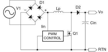
Boost Converter. The use of a boost preconverter with a voltage higher than the input voltage can help avoid harmonic emissions. Boost converters are used for PF correction in discontinuous and continuous modes. When used in a discontinuous mode, the transistor (MOSFET) is turned on when the inductor current reaches zero and turned off when it meets a certain reference. This causes the input current to follow the input voltage waveform and the PF to get close to 1. On the other hand, when the power level of a switched-mode power supply is greater than 300W, a boost converter operating in continuous mode is typically used. In this case, the current in the energy transfer inductor never reaches zero. Although boost-converters are better than other types of converters when applied to PF correction, their appropriate operation is only possible if the output voltage is higher than its input voltage.
Buck-Boost Converter. This topology is limited to few applications, since it presents reverse output voltage polarity and needs a floating driver for the power switch.
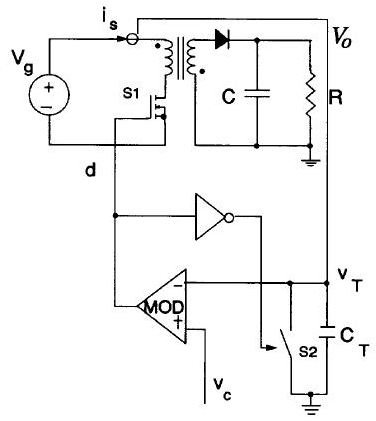
Flyback Converter. Flyback converters are commonly used for low power applications and are able to provide isolation and short-circuit protection with a single controllable switch. A MOSFET is used with dynamic control over the switch duty ratio to keep the output voltage at the desired level. In the discontinuous mode, the flyback converter operates by using a constant on-time control and a power factor equals to 1 can be achieved. In the continuous mode a charge control can be applied to the converter in order to achieve a unity PF.
References
Tang, W. et al, “Power Factor Correction with Flyback Converter Employing Charge Control”, APEC Conf. Proc. (1993): 293-298.
Wei, H., Batarseh, I., “Comparison of Basic Converter Topologies for Power Factor Correction”, Proceedings IEEE Southeastcon (1998): 348-353.
“Power Factor Correction (PFC) Handbook”, ON Semiconductor, Rev. 4 (2011).


