This article gives a clear idea about the procedure to dismantle, inspect, and assemble a shipboard refrigeration compressor (W-type reciprocating compressor).
Introduction to Refrigeration Compressor Overhaul
In this article we are going to discuss the detailed dismantling procedure, inspection, and assembling procedure of a refrigeration compressor as used on-board ships. As we all know that the refrigeration compressor is the heart of the refrigeration system. It basically does the following: takes suction from the evaporator and compresses it to increase its temperature and pressure so that the refrigerant will be able to circulate throughout the system. The basic function of using a refrigeration compressor is to provide the force required for the refrigerant to circulate.
As a part of maintenance it is a practice to overhaul the refrigeration compressor. In this article we will discuss the procedure to overhaul a refrigeration W-type reciprocating compressor.
Initial Checks before Overhauling
- Ensure that the entire system has been isolated.
- Ensure that no refrigeration vapor is present inside the compressor.
- Isolate the compressor from its prime mover and remove all electrical sensors.
- Don’t overhaul the compressor if required spares and tools are not available.
- Place a safety board stating “MEN AT WORK.”
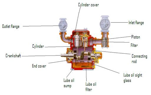
Refrigerator Compressor Sectional View:
Tools Required for Overhauling
- Box spanner set,
- Open and ring spanner (required size),
- Clearance measuring instruments, and
- Torque spanner.
Procedure to Dismantle
- Drain the lube oil completely before dismantling.
- Loosen all the bolts of the inlet and outlet pipes and remove the pipes and arrange them in a separate tray. Now remove the refrigerant filter.
- Loosen all the bolts on the cylinder head and remove them one by one. It is always a good practice to loosen the bolts diagonally.
- Now remove the cylinder head of all the units one by one.
- Loosen the bolts of the lube oil sump and remove the cover.
- Remove the shaft seal, end cover along with the lube oil gear pump, which is mounted on the same shaft.
- Remove the crankcase oil strainer from the crankcase.
- Remove the lube oil relief valve and the relief valve, which is used for the refrigerant. (Lube oil relief valve relieves excess lube oil pressure and the refrigerant relief valve relieves the excess gas pressure).
- Loosen the bottom end bearing nuts of all the units one by one and remove the bottom half. Don’t damage the bearing shell.
- Now the piston along with the connecting rod can be removed from the top without damaging the liner. Similarly remove the piston of all the units.
- Remove the liner along with the cylinder sleeve of all the units and place them in a tray.
- The unloader lift pin and the unloader assembly can be taken out.
- Now pull the crankshaft after removing the bearing.
Inspection
- Check the dimensions of the piston, liner, and connecting rod top and bottom shells and renew them if their wear down is not within the desired limit.
- Inspect the liner for any cracks and score marks.
- Ensure that the clearances are within the limit.
- Inspect the lube oil passages. The lube oil passages must be clear without any contaminants.
- Clean the filters if required.
- Check the condition of the suction valves and the discharge valves.
- Check the condition of the roller bearings. Rotate it manually and observe for any abnormal noise from the bearing. (An abnormal noise indicates that the bearing is not safe for use.)
- Check if the unloader mechanism is perfect.
- Clean all the parts.
Assembling Procedure
- Place the crankshaft along with the bearing.
- Place the liner along with its sleeve of all the units. Take care while replacing the liner.
- Place the unloading mechanism in its place.
- Place the piston and connecting rod of all the units from top and tighten the bottom end bearing. Maintain the torque as mentioned by the manufacturer in the manual. Lubricate the liner with enormous amount of oil so that the piston movement is smooth. Use guides for inserting the piston.
- Put the lube oil strainer, filter, both the relief valves, and cylinder covers of all the units and tighten them.
- Fix the end cover along with the lube oil pump and fix the shaft seal and their end covers.
- Fix the lube oil sump cover and tighten their bolts.
- Finally fix the inlet and outlet pipe connections.
- Fill the lube oil up to the desired level.
- Connect the prime mover and restore the electrical connections as per the diagram.
IMAGE CREDITS:
1. https://www.bfdibianchi.eu/immagini/mycom-W-Series-compressor-cutaway-view.gif