Offshore oil and gas installations have runway beams and padeyes mainly for removing equipment for maintenance. These appliances must be load-tested and this can be carried out at the offshore construction yard using test weights. Following a successful load test, a load test certificate is issued.
Oil and Gas offshore production platforms have many pieces of equipment such as pumps, generators, large valves, and pipelines. To service these components or remove them to the workshops, a lifting appliance is required. The vast majority of the components are serviced with an overhead runway beam with a dedicated trolley.
These are normally load tested and certified at the construction yard during the construction phase, preferably before the equipment is installed below them. This will avoid any damage to the equipment during load testing should any part of the lifting appliances fail and make the test easier to carry out without clambering over equipment.
The test weights are normally fabricated from steel plates, and certified by the yard engineer and Certifying Authority.
A temporary trolley and chain-block is used for the load testing in place of the dedicated set as these will have been tested at the manufacturers and come fully certified.
Runway beams are tested to BS2853 (1957) design and testing of steel overhead Runway Beams.
This is another article in my series on load testing of offshore lifting equipment, and we begin by having a look at the first steps in the procedure…..
Pre-Loadtest Runway Beams Inspection
The runway beams are subject to a thorough inspection by a competent person, and it includes the following:
- Check all bolting is of high tensile B6 bolts, nuts and tapered washers and are tight
- End stops bolted securely
- Check and verify the runway beam I/D number stamped on the beam
- Check that the load cell has current calibration certs
- Check that temporary chain block and pulley is certified
- Calculate the deflection under SWL & Proof Loads
- Check test weights are certified
- Check a pre-test survey of the position of the beams has been carried out
- Check that a pre-test NDT has been carried out on the beam connections to the structure
Load Test Procedure
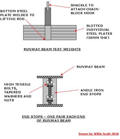
Test Weights
The load-test weights can be hired, these are normally bags which when at the location are filled with water until the correct weight is reached. However we had plenty of scrap plates knocking about in the yard so we made our own steel testweights. The individual plates were slotted and fed through a lifting frame to facilitate adding or removing to achieve the desired test weights.
Procedure
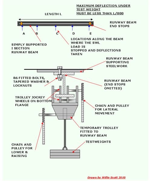
The end stops at one end are removed and the temporary trolley and chain-blocks are fitted to the beam, the end stops are then replaced.
The trolley is positioned as close as possible to the end stop at one end of the beam and the SWL lifted off the deck using the chain-block. Once the weight is clear of the deck the beam is again surveyed and any deflection recorded.
This is repeated at several points along the beam, right to the other end stop, the deflections being noted and then the SWL test weight removed. The beam is then resurveyed for any permanent set.
The proof load is then attached to the chain-blocks and lifted clear of the deck, and traversed along the beam. It is stopped at the location where the maximum deflection was recorded under the SWL testweight, and the deflection recorded.
The testweight and trolley is then removed, the end stop refitted and the beam dimensionally resurveyed. NDT is carried out once more on the attachment welds to ensure no cracking has occurred during the test.
A thorough physical examination of the beam is carried out, checking all bolting and end stops are still securely fitted.
Once the surveys and NDT report has been received, and a successful test indicated the beam can be painted yellow, the unique I/D No and SWL is stencilled in large black lettering on both sides. Once this is complete a Runway Beam Load-Test Certificate can be issued, signed by the Mechanical Engineer and the Certifying Authority.
Calculating Runway Beam Deflection Under Load
The maximum deflection recorded on the beam whilst under the SWL and Proof Load must not be more than 1/800 of the beam length. This can also be calculated using the formulae below which will give the deflection for a simply supported I beam under various loads.
δ= WL3
48EI
Where
δ = Deflection
W= Testweight
L = Length of beam
E = Modulus of Elasticity
I = Second moment of area of section
So if we had a simply supported I beam of (18x76) section, 18 foot long and a proof load of 20T is applied,
δ = 20 x 2240 x 183
48x 306 x 13304
= 261273600
= 2916000000
= 0.09”
Permitted deflection = L/800
= 18 x 12 /800
= 0.2"
So the beam deflection is well within the allowed tolerences.
Note This calculation is equally valid using metric units.
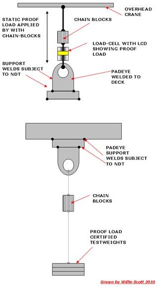
Load Testing of Padeyes
Load-testing of Padeyes
Padeyes are welded above equipment where a vertical lift only is required, usually located above heavy valves or compact pump units.
Padeyes welded on the deck are used to secure loose equipment such as inflatable liferafts or rope ladders and to secure tie wires.
They are both static load tested using the proof loads being witnessed by the Certifying Authotity (see sketches in image section)
Load-testing Padeyes Above Equipment
The padeye i/d is stamped onto the padeye using soft nose stamps. (I used to request the padeyes stamped both faces when being fabricated at the plate shop.) They are welded to the support structure above the equipment and this welding is subjected to pre-test NDT.
The proof is suspended from the padeye for a few minutes then removed. The attachment is then subjected to post test NDT. Following successful NDT report, the padeye can be painted yellow, with the I/D and SWL stencilled alongside, a Padeye Load-test Certificate can be issued.
Load-testing Padeyes Welded to Deck
These are fabricated and hard stamped with I/D No, and welded to the deck, and post test NDT carried out on the attachment welds.
Most of these padeyes can be load tested using an overhead crane, with a load-cell between the crane hook and the padeye. Some are inaccessible by crane so a small hydraulic jack can be used to simulate a static load condition, and support welding subjected to post test NDT. As before once NDT clear report has been issued the padeyes are painted yellow and a padeye Load-test Certificate issued.
All padeye load test certification packages will be sent offshore at sailaway.
Reference Webs Visited
Apds-vn: Testing of Offshore Equipment:
Runway Beams and Padeyes Under going Load-test