What is shaft alignment and why is it important? What are the main types of alignment techniques?
Overview
All types of machines having shafts as an integral part of their structure, experience problems related to shaft alignment. Shaft alignment is a method or procedure by which shafts of machines such as motors and turbines are connected to a generator or pump in proper alignment. Improper alignment leads to increase of stresses in the shafts and thus on the equipment, which might result in break down of the machine.
Alignment of the shaft is necessary when the motor or driven machinery is new or when it is dismantled due to improper running. Moreover, as the name suggests, the main purpose of shaft alignment is to make sure that the center line of the motor rotor shaft coincides with the center line of the driven machinery i.e., pump or a generator. Thus, alignment is necessary to prevent vibrations and also to facilitate smooth running of the shaft.
The ship’s engine room is full of such rotating equipment such as pumps , generators and so forth. It is therefore necessary for a marine engineer to have thorough knowledge about shaft alignment methods, techniques and concepts.
Types of Misalignments
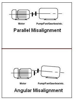
Before we start learning about the procedure for alignment it is very important that we first know the types of misalignments. Generally there are two main types of misalignments
- parallel (also known as offset)
- angular (also known as gap)
In parallel misalignment, the two shafts to be aligned have centerlines that are parallel to each other but are in offset condition.
In angular misalignment the axis of the two shafts are located at an angle to each other.
Both these types of misalignments are shown in the adjacent sketch that will give a visual idea to the reader as to what is being talked about.
So how is alignment basically done and what are the main methods to carry it out? Read on
Types of Alignment
Alignment of the shaft is possible only if the two ends of the shaft are not bent or crooked but faces each other in perfect symmetry. Now these two ends when to be aligned can be done in two main methods.
- Offset alignment
- Angular alignment
It is to note that none of the alignment is perfect. This means that all the alignments are rough alignments done with the help of a straight edge ruler or a filler gauges. However, precision alignments are possible using dial gauges with magnetic bases.
Offset Alignment
Offset alignment or radial alignment is checked using a straight edge ruler. This is done by placing the ruler at various parts of the coupling halves, that is to say at the following sides
- top
- bottom
- adjacent
- opposite
Any gap between the shafts will indicate that the shaft is offset or misaligned slightly and it needs to be rectified. This misalignment can be rectified by adjusting the motor or by raising the platform of the motor or driven machine using shims.
Angular Alignment
This method can be used by inserting a feeler gauge and here are the steps listed below.
- Insert the feeler gauge between the coupling faces of the shafts
- After the feeler gauge is put, both couplings are rotated half way simultaneously
- The readings on the feeler gauge are checked at four points on the shaft coupling
- Any difference in the reading indicates that there is an angular displacement between the shafts
- The misalignment can be corrected by lifting the machinery or by using shims underneath the platform
In order to prevent any kind of misalignment from re-occurring, the motor and the driven machinery should be solidly bolted to the base of the machine after the final positions of both, the motor and driven machinery are decided.
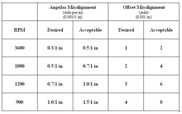
Typical Alignment Tolerances
Although it is not possible to put forth a general statement covering all types of machines and situations, yet the chart given below should give a rough idea to the engineers regarding alignment allowances. Of course this information must be augmented with one’s own knowledge, experience plus values given by the manufacturers and operating manuals for machines.
References
Piotrowski, J. (2006) Shaft Alignment Handbook, 3rd Ed. New York: Marcel Dekker Inc