Learn about the mechanism used to deliver fuel to individual units in the engine
Introduction
The fuel injection system is one of the most important parts of a marine diesel engine . A fuel injection system does the work of providing the right amount of fuel to the engine cylinder at the right moment. It is also extremely important that the fuel injected inside the engine enters the cylinder at the right combustion situation for the highest combustion efficiency. It is for this reason that there is a need of a measured fuel supply system which times and monitors the delivery of the fuel and oil in the combustion chamber. This timing device helps to have a perfect atomization of the fuel. The device is known as fuel injector.
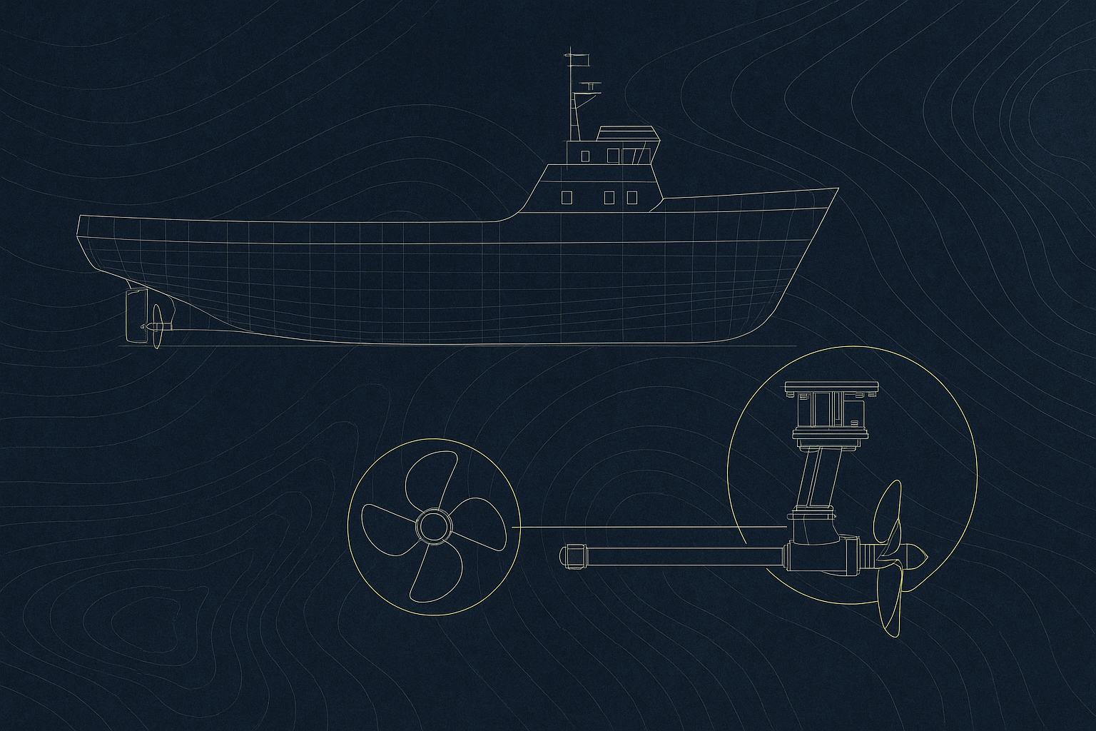
Fuel injection is done with the help of cams and camshaft. The speed of the cam shaft is same as the engine speed in a two stroke engine and half the engine speed in a four stroke engine. The adjacent fuel injection system diagram gives a broad view to the reader regarding the fuel injection system. The faded sketch shows the engine in the background whilst the dark coloured schematic represents the fuel system. This helps the reader to understand the concept in conjunction with the given theory.
The injection system comprises of the most important part which combines both mechanical and hydraulic operation. This is known as the Jerk Pump
Jerk Pump
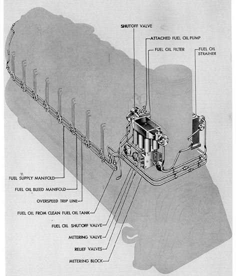
The Jerk pump system consists of individual fuel injectors for each cylinder. This means that the injection of each cylinder is exclusive of each other. The injector pump is operated once every cycle using the cam and cam shaft. In order to ensure that the camshaft and the injection runs simultaneously to deliver perfect timing of fuel injection, the barrel and plunger of the injector pumps are selected of appropriated size to suit the engine fuel requirements. The fuel delivery is facilitated with the help of ports in the barrel and slots in the plunger or adjustable spill valves.
All the injector valves are preset to a specific pressure. The needle of the valve lifts exactly to this pre-set pressure, ensuring that the fuel completely atomizes once it enters the cylinder.
The fuel pumps are generally of two types:
- Valve control discharge type
- Helix or helical edge pump
The valve control discharge type pump is generally found on slow speed two-stroke engines and the helix type are found on high or medium speed four stroke engine.
Common Rail
In the common rail system, each cylinder doesn’t have an individual fuel pump but only one high-pressure multiple fuel plunger pump for all the cylinders. A manifold or rail is where the fuel accumulates at high pressure before entering the cylinders. This common rail supply fuel to all the cylinders. A timing valve in provided between the rail and the injector to control the timing and extent of fuel delivery. The common rail is also provided with spill valves to release excess pressure. The injectors in a common rail system are often known as fuel valves.
If you would be interested to read an article dealing in more detail about the Common Rail Injection System , read this article.
Image Credits
San Francisco Maritime National Park Association Website