The Rotating Arm Facility is a Ship Motion Test, which is meant to measure hydrodynamic forces and moments. The article guides you with the working phenomena and the determination of the derivatives too.
What is the Rotating Arm Facility?
The Rotating Arm Facility is a Ship Motion Test, which is meant to measure hydrodynamic forces and moments. This test is also used to perform captive-model stability, control and propulsion tests on towed bodies, surface ships, unmanned underwater vehicles, submarines, swimmer delivery vehicles and also on other sub-sea vehicles. As the name itself clarifies, the models are towed in circular orbits or paths across still water, and all this is done by the help of a rotating arm.
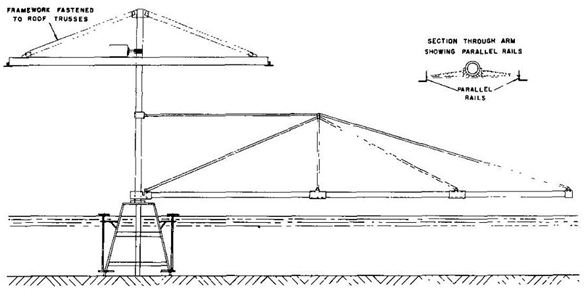
The adjacent sketch shows the schematic of a rotating arm facility which is as old as 1945
Construction and Working Technology
The surface models up to a length of 30 feet and submerged models up to about 22 feet can be tested keeping in mind a wide range of angles of attack and drift, all in a controlled environment. Datas are being obtained over a wide range of angles of attack, angular velocities and turning radii. In one-half revolution of a radius of 120 feet, steady-state speeds up to 30 knots can be obtained and speeds up to 50 knots of the same radius is obtained in approximately two revolutions. The facility is performed in a circular sea-basin of diameter 260 feet and a depth of 20 feet and the models are towed in circular paths through the still water of the basin at predetermined turning rates or angular velocities by a horizontal, radial structure called the Rotating Arm.
Determination of the Derivatives Yr and Nr
The Rotating Arm Technique measures the rotary derivatives, or more specifically the Yr and Nr on the models, which is a specially arranged towing tank and apparatus. The model is being fixed to the end of a radial arm and an angular velocity is applied on it by rotating the arm through a vertical axis fixed in the tank. The orientation of the model is such that its x-axis and z-axis is kept normal to the radial arm and is attached to the arm at the model’s mid-length.
As a result of this orientation, when the model revolves about the axis of the tank, it rotates at the rate r. At this point however, the transverse velocity component v of the model is always zero (yaw angle of attack β=0) and the axial velocity component u1 is same to its linear speed. The model is constantly rotated at a constant linear speed and various radii R.
The dynamometer then measures the force Y and the momentum N that is acting on the model. Finally, by assigning the slopes at r=0, the derivatives Yr and Nr are obtained. Besides determining Yr and Nr, the Rotating Arm Facility can also be used to obtain Yv and Nv as well. If you plot the obtained values of Yv and Nv corresponding to each r value against r, you can obtainn the values of Yv and Nv at r=o.
References
Image of Rotating Arm Sketch - The American Society of Mechanical Engineers (1981) International Historic Mechanical Engineering Landmark: Rotating-Arm Model-Test Facility. New York