The large quantity of sea water which is required to cool the scrubber also needs to be drained back to the sea, apart from the deck sealing water which is of relatively lesser volume. Learn about the effluent drainage system of Inert Gas (IG) systems in this article.
Introduction
In the previous article we saw the analyzing instruments used for measuring oxygen and hydrocarbon vapour levels in the IG system on board ships. We know that the scrubber utilizes large quantities of sea water for cooling and cleaning the flue gases and the effluent needs to be discharged back to the sea and there should exist appropriate arrangements for the same as mentioned below.
Drainage System and Seawater Arrangements
Drainage System
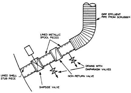
The overall drainage system has been outlined in the diagram below which is clearly labelled to show the various parts and is fairly self descriptive. The system consits of a combination of a non return valve and a ship side valve which is mandatory to be controllable both from within and outside the engine room or machinery spaces. The drains on the metallic spool linings also have non return valves fitted in them. The main idea behind having these spools is to facilitate the removal of the valves in the pipeline for removal.
The diameter of the pipe should be compatible with the water volumes associated with the scrubber which is kept in mind while designing the same. The material used for effluent piping is normally carbon steel or any other suitable material which has an internal protective layer. This is necessary since the sea water on its return consists of various dissolved impurities which are corossive in nature.
Also there is a separate drain arrangement for deck seal water which is not shown in the diagram since it is deliberately kept separate from the main drain system of the IG scrubber because the deck water seal is located in the hazardous zone while the engine room comes in the safe zone.
Seawater Arrangements
Regulation 62.6.1 of SOLAS mandates the inflow of sea water to the scrubber to be supplied via an independent pump which is separate from other systems such as fire pumps and so forth, though there should be arrangements for using them as alternative source of water in case of emergency when something goes wrong with the main scrubber pump. Similarly there should be a pair of pumps to supply sea water to the deck seal for safety purposes.
Since the suction of the pumps drawing water from the sea varies with the depth to which the ship is immersed within the sea, the scrubber pump and the deck seal pumps should be able to provide sufficient quantities of water even at light weight conditions when the ship is floating high known technically as light draught conditions. Apart from that there are several points which need to be kept in mind while designing these piping systems. For example there need to be loops in the deck seal piping so that any possible accidental backflow of gases is prevented.
After having learnt so much about the inert gas system and its principles, working and design in last few articles, it is now time to proceed to know about the actual operation of the IG plant in our next article .
Reference
Images of Scrubber Effluent Drainage System - Transport Canada. STANDARD FOR INERT GAS SYSTEMS. SHIP SAFETY BRANCH. SEPTEMBER, 1984. TP 4295 E