Indicator diagrams are indicative of the power generated within engines and are a useful tool for marine engineers to know how well their engines are performing. Learn more about them inside.
Introduction
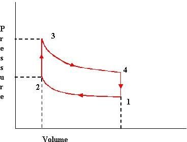
We know that a P-V diagram contains a plot of the pressure and volume variations for an engine. The significance of this chart lies in the fact that the work done during the cycle can be gauged from the area enclosed within the loop of the graph. Let us study about the indicator diagrams in bit more detail in this article.
Indicator Diagram
The term indicated power refers to the theoretical power that develops inside the cylinder of an engine though in actual practice the power available at the outside (brake power) is lesser but for the time being we will not consider the latter but only talk about indicated power. The best way to find out the indicated power is from calculating the area under indicator diagram. But how is an indicated diagram drawn for an actual engine. Just take a look at the left hand side of this text to find out how an indicator diagram looks. Actually you will notice that it is the same P-V diagram which we studied in the previous articles relating to various types of marine diesel engine cycles such as diesel cycle , dual cycle and Otto cycle .
Engine Indicator
Just take a look at the figure to see what an engine indicator looks like. As the name suggests it is used to draw the
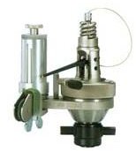
indicator diagram for an actual engine while it is firing (working). The black coloured handle you see at the bottom of the instrument helps to fit this instrument in the appropriate slot in the cylinder head known as the indicator cock. Once the arrangement is in place the piston inside the instrument is exposed to the pressure variations happening inside the cylinder and these are them transferred on to a paper through the stylus which moves in proportion to the movement of the piston and the spring on top which opposes the instrument piston movement.
Limitations
Although it is a good instrument to measure power basically its use is limited to measuring indicated power of large slow speed engines only, which in the marine context means the main propulsion plant of the ship. Several factors such as spring inertia and stylus movement limit the diagrams in case of high speed engines for which separate indirect methods are used to measure power.
In the next article we will learn the procedure of using an engine indicator to actually draw the diagram for a large slow speed marine diesel engine.