The involute gear is very popular in industry. In this gear design article, we will define the involute gear and will discuss the design, applications, and advantages of the involute gear.
Based upon the profile of the spur gear teeth, gear can be classified in two major categories: involute gear and cycloidal gear.
How the Involute Gear Teeth Profile are Generated
Geometrically an involute curve can be generated by the locus of the end point of a virtual taut string unwinding from its circular roll. Another way of visualizing the involute curve is visualizing the locus of the end point of a stick, moving around the periphery of a wheel without slipping. The involute curve generating process we have just discussed will create a curve like below:
How to Create Involute Gear Teeth Profile Using CAD Packages
Using AutoCAD or any of the 2D CAD package you can create involute gear teeth. Before going further, let’s assume the following data:
- Root circle diameter (R1) = 14 mm
- Base circle diameter (R2) = 15.34 mm
- Pitch circle diameter (R3) = 15.87 mm
- Outside diameter (R4) = 17.46 mm
- Number of teeth (N) = 18
Now, let’s go to the actual procedure:
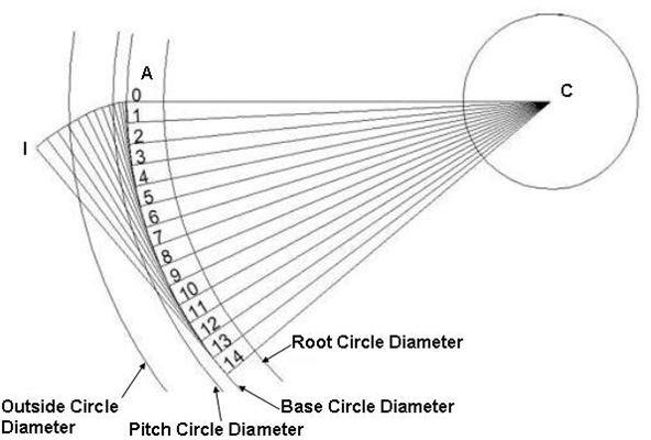
- Draw the root circle, base circle, pitch circle and the outside diameter with common centre.
- Draw a horizontal line (ACB) passing through the centre and touching the outside diameter.
- Trim the left side of the line after the centre. Now the line becomes AC.
- Draw a small perpendicular line (AD) to the line AC and at the point A. The length of the line AD is equal to 1/40 times the diameter of the base circle or equals to 0.38 mm.
- Now, calculate:
θ = 360/ (Π* 40) Degree
= 2.86 Degree
This θ will be used later in the process of the involute curve generation.
-
Radially copy the lines AD and AC fourteen times with spacing between them of 2.86 degrees.
-
Number the lines by 0, 1 …..14.
-
Now, you have to increase the lengths of the small lines (AD). How long? Multiply the original length of each line with its index. So, the length of the 0th line will be 0, the length of the 1st line will be 0.38mm, the length of the 2nd line will be 0.76mm and so on. Similarly the length of the 14th line will be 5.32 mm.
-
Join the end points of the each line by smooth curve and you will get a curve (AI) involute like below:
-
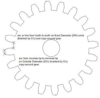
Now, trim the involute curve beyond the outside diameter.
-
Draw a line (EA) joining the intersecting point of the involute curve and the centre. Radially, copy the line by ¼ times the angular pitch. For us the angular pitch is 180. So we will copy the line by 4.50. Now mirror the line EA and the involute curve AI.
-
Now trim the unnecessary lines and you can see one involute gear tooth. Copy the tooth radially 18 times and you will see the involute gear. Like below:
Manufacturing Process
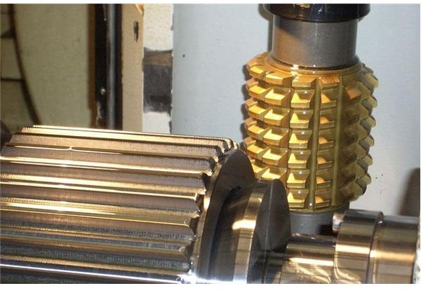
Involute gears are manufactured by gear hobbing process . The cutting tool is called hob. The hob looks somewhat like a worm gear with non-continuous and hard threads.
Imagine you have a steel made worm gear engaged with a thick wax disk and axis of the worm gear and the wax disk is perpendicular to each other. Now, if you rotate the worm gear you will see gear teeth are being generated to the wax disk. The hobbing process is exactly similar to this. You will have a single thread cutter (hob) engaged with a blank (tooth less gear), the angle between the axis of blank and that of hob depends upon the helix angle of the spur gear to be generated.
Look at the typical hobbing machine arrangement is below:
Advantages of Involute Gears
- The contact between two mating involute gear tooth moves along a fixed plane of contact irrespective of the centre to centre distance of the gears. Thus involute gears can handle centre shifts or you will get greater assembly flexibility.
- Contact surface is always perpendicular to the plane of contact, this helps reducing torque variation and thus involute gear gives silent operation.
- Manufacturing fairly accurate gears of this type are quite easier by hobbing process.
Disadvantages of Involute Gears
- Not suitable for lesser numbers of teeth.
- Undercut or interference between the teeth may occur for this gear in case addendum modifications are not performed properly.
- Proper lubrication is required for avoiding the high localized stress.
Application
Except very small gears (used in watches, toys, and electronics instruments), almost all the gears you will see in automobiles, earth moving equipment, and production machines are of involute gear.
Conclusion
The involute gear is one of the most widely used gears in industry. Ease of manufacturing, silent operation, and ease of assembly are the major advantage of using involute gears. Hoewever, the involute gear has a problem of undercut and overheating. So, while doing gear box design you must see if an involute gear is really suits your application or not.


