Worm gears are widely used in industrial settings and in automobile gear boxes. This worm gear design tutorial will discuss the basics of the worm gear box design calculation using the AGMA empirical formula.
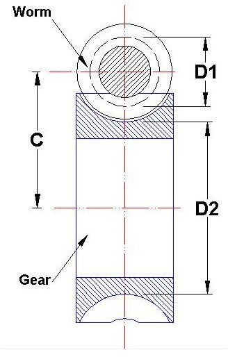
A worm gear box must contain a worm and a mating gear (helical gear) and normally the axis of the worm is perpendicular to the axis of the gear. Look at the picture below:
Where,
D1 – Pitch Diameter of Worm
D2 – Pitch Diameter of Gear
C – Centre to Centre Distance between the Worm and the Gear
This worm gear design tutorial will discuss up to the selection of the module and pitch and the calculation of the number of teeth, pitch circle diameter and centre to centre distance between the worm and gear. We will use the AGMA formulae for doing the calculations. Design calculations of the other aspects of the worm gear will be discussed in a subsequent part of the tutorial.
Steps of the Design Calculation
- The axial pitch of the worm and the circular pitch of the gear must be same for a mating worm and gear. We will use the term Pitch (P) for both the pitch in this tutorial.
- Also, the module of the worm as well as the gear must be equal for a mating worm and gear.
- Now, let’s say we have the following design input:
Speed of the Worm (N1) = 20 RPM
Speed of the Gear (N2) = 4 RPM
-
And, we have to find out the Module (m), Pitch (P), Number of helix of Worm (T1), Number of teeth of Gear (T2), Pitch circle diameter of Worm (D1), Pitch circle diameter of Gear (D2), Centre to centre distance(C).
-
Select the suitable module and its corresponding pitch from the following AGMA specified table:
Module m (in MM) - Pitch P (in MM)
2 ————————-6.238
2.5 ———————- 7.854
3.15 ——————— 9.896
4 ————————- 12.566
5 ————————- 15.708
6.3 ———————– 19.792
8 ————————– 25.133
10 ————————- 31.416
12.5 ———————– 39.27
16 ————————– 50.625
20 ————————– 62.832
-
Say, we are going ahead with the Module as 2 and the Pitch as 6.238.
-
Use the following gear design equation:
N1/N2 = T2/T1
And, we will get:
T2 = 5 * T1……………….Eqn.1
- Now use the following AGMA empirical formula:
T1 + T2 > 40………………Eqn.2
- By using the two equations (Eqn.1 & Eqn.2), we will get the approximate values of
T1 = 7 and T2 = 35
- Calculate the pitch circle diameter of the worm (D1) by using the below AGMA empirical formula:
D1 = 2.4 P + 1.1
= 16.0712 mm
- The following AGMA empirical formula to be used for calculating the pitch circle diameter of the gear (D2):
D2 = T2*P/3.14
= 69.53185 mm
- Now, we can calculate the centre to centre distance (C) by the following equation:
C = (D1 + D2)/2
= 42.80152 mm
- The below empirical formula is the cross check for the correctness of the whole design calculation:
(C^0.875)/2 <= D1 <= (C^0.875)/1.07
Observe that our D1 value is falling in the range.
Conclusion
The worm gear box design calculation explained here uses the AGMA empirical formulas. A few worm gear design calculator are available on web, and some of them are free as well.
In the next worm gear box design calculation tutorial we will discuss the force analysis of a worm gear box.
Related Reading
Helical Gear vs. Spur Gear : If you have observed a spur gear application, you may have noticed that spur gear can be replaced by helical gear. Where should a helical gear should be used? What are the benefits and disadvantages of doing so?


