The universal testing machine for checking various electrical auto parts presented here can definitely become priced equipment for garages or even auto parts manufacturing company. Complete wiring details are comprehensively discussed in this article.
An automobile can be totally incomplete without its electrical systems. Whether it’s the lights, ignition system, or the electronic gadgets, all require power and many associated electrical accessories for their proper functioning. With so many electrical parameters involved, problems and malfunctions can be always on the cards. Moreover verifying the correct working of a component also becomes imperative while replacing a faulty one in a vehicle. The most commonly used and vulnerable parts of auto electrical are the lamps, fuses, wires, CDI unit, ignition coil, flasher unit, rectifier, switches, horns, etc.
The simple universal testing machine design presented here may be ideally used for testing the above discussed components and is especially suited for the auto parts industry and garages.
Let’s study its wiring details.
Circuit Description
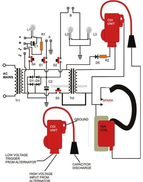
The figure shows a comprehensive design of the proposed unit. The wirings involved are in fact very basic and shouldn’t require much of an effort in completing it.
Beginning from the extreme left we see a regular transformer bridge power supply configuration powering the entire system. The components used here are high current heavy duty type for enabling correct testing of powerful head lamps and horns.
The line terminating via switch S1 is used for checking parts which operate at direct 12 V DC like lamps, horns, etc. After connecting the relevant part at the point A, pressing S1 momentarily confirms its functioning.
A small circuit comprising L1, C1, R1 helps to locate possible faults in rectifiers. A rectifier normally carry four terminals, two AC inputs marked “≈ “ and two output terminals having the signs “+” and “-“.
Testing it here will just require connecting its points into the relevant pin-outs appropriately. Pressing S4 may provide a couple of results – a momentary illumination of L1 shows correctness of the rectifier, any other result indicates a fault in the connected device.
Testing a flasher unit is also very simple. Fixing its terminals at point B and pressing S2 should make L2 and L3 flash at the particular rate, displaying a good flasher; any other doubtful condition indicates a possible circuit fault of the unit.
The wiring at the extreme right specifically deals with the testing of the ignition components like the CDI unit and the ignition coil (shown in RED).
As can be seen in the diagram, a 12 volt AC is taken from TR1 and is fed to a rather smaller 12V transformer’s secondary winding. The voltage is appropriately stepped up to the rated value and this voltage becomes the sample voltage for the CDI unit’s AC input. It gets stored inside a high voltage capacitor inside the CDI unit. This voltage is pulsed back intermittently in response to the gate triggers derived from TR2 itself via D5 into the primary winding of the ignition coil.
The above pulses are hugely stepped-up to monstrous levels and are pumped out through a well-insulated and layered wire output into the sparking contacts where ultimately it gets converted into high-voltage arcing. The sparking elements can be made by fixing two parallel copper nails over an insulated firm base at about a centimeter apart.
Remember the arcing generated from the ignition wire contains dangerous high voltages, having potentials of paralyzing any body part coming in contact with it , and may even cause death to an individual suffering from cardiac weaknesses, so extreme care should be enforced while building or using this automobile universal testing machine.
Basically the above process is the replica of exactly what takes place inside a vehicle’s ignition system; the generated spark is ultimately used for triggering the ignition of the vehicle.
Since here the CDI unit and the ignition coil both complement each other, checking any one of them would require connecting the other complimenting component first (a confirmed good one) and vice versa. The relevant device may be checked by pressing S3 - continuous sparking indicates a good device, other results show it to be faulty.
If you are wanting to test a CDI unit different from that shown in the diagram, you will need to identify its outputs and inputs appropriately before connecting – you may need the help of a qualified motor mechanic for this.
Parts List
The following parts will be required to build the above discussed unit.
R1, R2 = 10K,
C1, C2 = 2200uF/25V,
D1…D4 = 1N5408,
L1 = 12 V, small lamp (as used in car dashboard indicators)
L2, L3 = Automobile side indicator lamps.
TR1 = 0-12V, 5 Amp.
TR2 = 0-12V, 1Amp.
CDI and Ignition Coil are types as used in motorbikes, one may easily replace them with other complementary types.
Spark Contacts = See text.
Sundries = Appropriate metallic enclosure, mains cord, LEDs, Fuse, external sockets, etc.


