A commercial variable voltage autotransformer is a costly device to procure. However through some simple interlinking of a couple of ordinary transformers, different levels of mains voltages quite comparable to the above may be obtained. The complete procedure is explained herein.
A variable voltage autotransformer (also known as variac) is a transformer which is able to transform or produce AC mains voltages at different desired levels at its output. Thus unlike an ordinary transformer its output voltage is not fixed, rather can be varied manually to obtain more than a single voltage. The voltage obtained from such a device is normally an AC at mains level, which may be higher or lower than the applied input voltage depending upon its settings.
You may already be familiar with the conventionally available autotransformers, which are normally toroidal in shape and having a large knob on the top surface. The body is basically made up of a laminated iron core with hundreds of copper windings well secured inside a metal frame.
When an AC mains voltage is applied to its terminals, each of its windings is subjected to different discrete levels of voltage through magnetic induction, generated by the interaction between the iron core and the windings. The central shaft or the knob is mechanized in such a way that when it’s rotated, it uniformly selects each subsequent copper winding smoothly and produces the corresponding voltage levels at its terminated output. This voltage may range right from zero to the maximum applied input voltage and above.
Wiring a Homemade Variable Autotransformer
Although constructing the above type of an autotransformer at home would be impossible and unaffordable, using a few normal step-down transformers and wiring those up through some smart configurations can provide you with selectable voltages that may be lower, equal, or higher than the normally available AC.
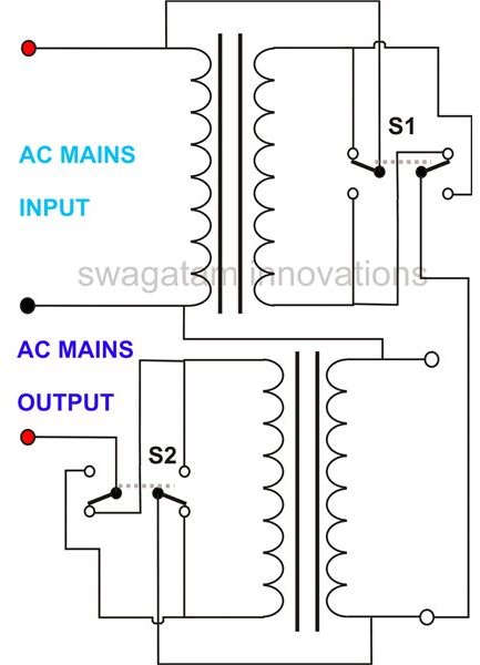
Referring to the diagram we see a couple of ordinary step-down transformers wired up in series through switches which are used to step up or step down the output voltages. Let’s try to understand the operation through the following explanation:
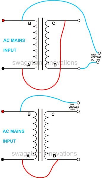
Just like many electronic components, transformers too have polarities within their two windings. When AC is applied to the primary winding of a transformer, an instantaneous positive current (positive half cycle) flowing from the lower terminal A towards the upper terminal B in the primary winding, will generate an instantaneous induced positive current flow exactly in the opposite direction, i.e. from the upper terminal C towards the lower terminal D in the secondary winding.
We know that when we connect two batteries in series with one battery’s anode touching the second battery’s cathode, we are able to sum up or add up their individual voltages together at their free ends and vice versa.
Similarly, in the above case if we connect the end A of the primary winding to the end C of the secondary winding, we can add up the rated secondary voltage with the input AC supply, i.e. if the secondary rating is 0-12V and the applied input is 220 Volts, the obtained output here will be around 232 Volts across the free ends of the transformer.
Conversely, if we connect end A to the end D, the secondary voltage gets deducted from the input AC and the resultant output becomes 208 Volts across the free ends of the transformer.
In the present design of a variable voltage autotransformer switches S1 and S2 conduct the operations exactly as explained above and we are able to get different levels of voltages at the output. Here we use two transformers just to make the output range wider and receive voltages much higher or lower than the applied input AC voltage.
In voltage stabilizer circuits the same concept is exploited, the only difference being that the switching there is automatically done.
References
-
Authors own experience.
Images - Drawn by the author.


