A single IC 4017 is able to produce 10 sequentially shifting logic high outputs, which may be used for creating dazzling chasing LED lights. However integrating two ICs can provide you with 18 amazing sequential outputs. The article illuminates a simple method of cascading 4017 ICs.
Operating 4017 ICs in Series
The only way of describing the IC 4017 is: “they are simply amazing.” A creative electronic enthusiast will exactly know how versatile this IC is, and there can be practically innumerable different circuit configurations possible using this priceless IC.
Technically, it is a “divide by 10 Johnson decade counter/divider IC .” The name may seem a bit confusing for newcomers.
In simple terms, the IC responds to a frequency at its “clock” input and produces a sequential 10 logic high pulses through its 10 individual outputs. Thus the IC counts up to 10 to complete ONE full cycle of its output sequence in response to an input of TEN individual pulses and hence the name “divide by 10.”
We have already discussed an interesting an amusing light chaser circuit using this IC and seen it illuminating 10 LEDs in sequence in response to the set input frequency through an external oscillator circuit. However, instinctively we seem to be never satisfied and hence 10 numbers of outputs is now not looking so impressive. So what do we do? Simple, we try to make it a double.
By cascading 4017 ICs (two of them) we can very easily achieve 18 sequencing outputs if not 20. Here we discuss how a couple of 4017 may be cascaded together through a handful of other passive and active components to generate the illusive 10 plus sequencing outputs.
Circuit Description
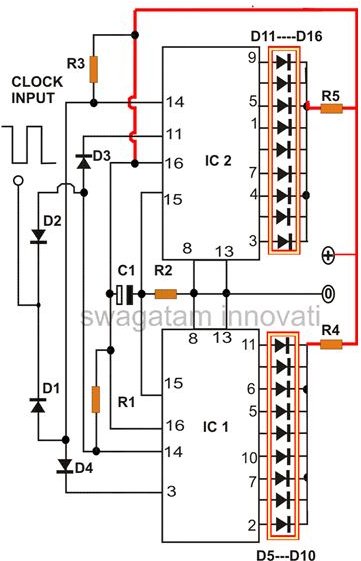
Looking at the figure alongside, we see some important configurations done around two 4017 ICs pin-outs. Let’s try to understand them in a step wise manner:
Pin #16 is the positive and pin #8 is the negative and are connected to their respective positions.
Pin #13 is also grounded; not following this would latch the output and stop its proceeding.
All the outputs as shown in the figure are terminated with LEDs, so that the shifting sequence may be visualized.
Pin #15 is the reset input and requires to be grounded and therefore is pulled to the grounded level via R1.
Interestingly a capacitor C1 is connected across the positive and the pin #15. When power is switched ON, instantaneously the voltage passes through this capacitor and reaches pin #15 to reset it. Resetting the IC makes it sure that the sequence begins from the first pin onwards which is #3 and not from any other intermediate pin-out.
Pin #14 which is the clock inputs of the ICs are permanently held at the positive supply level via R2 and R3. It means, now it will respond only to the falling edges of the input pulses or in simple words to the negative pulses.
You may build an oscillator circuit by using either IC 4049 , 4060 or 4093 , for driving the present circuit.
Now, when power is switched ON, as explained above the ICs are reset and their the sequence initiates from pin #3 which is the first pin of the sequence in response to the clock input at pin #14.
However, at this instant except pin #3 rest all other pin-outs are at logic low level and so is pin #11 of IC 2.
This simply means that at this instant the clock input pin #14 of IC1 is rendered inactive, because it is permanently held to ground via D3 and pin #11 of IC 2 and thus cannot respond to the input clocks.
But IC 2 is free to move and its outputs start shifting sequentially until it reaches its last pin #11 when it becomes high and releases pin #14 of IC1.
IC1 now initiates, but the moment the logic level from its pin #3 flips from high to low, pin #14 of IC2 this time is rendered inactive and is clamped via D4 and pin #3 of IC1.
In the meantime, IC1 continues its output’s sequential journey until again its pin #3 becomes high and the cycle is repeated.
The above configuration results in a continuous sequence of shifting logic high pulses from both the ICs in 18 steps. That’s exactly what we were looking for.
Parts List
For cascading 4017 ICs and producing the required light chaser outputs, you will need the following handfull of components:
All resistors are 1K, 1/4 watts, 5%, CFR,
C1 = 1uF/25V,
All Diodes are 1N4148,
D5—-D16 = LEDs, color as per choice
IC1 and 2 are 4017, decade counter/divider


