
When more frequent and regular operation is involved, powering a green laser pointer externally can save you the headache of changing its batteries every week. A simple power supply circuit explained here is suited for the critical operation of powering a modified green laser pointer.
Introduction
Laser beams are particularly renowned for their powerful beam intensities which are able to sustain straight paths through unlimited distances and create a tight spot as they strike an opaque object. This may remind you of Steven Seagal, William Baldwin , Bruce Willis, and many other Hollywood Stars who are shown during many occasions (in movies) getting that dreaded red spot on their body from a remotely located sniper’s gun.
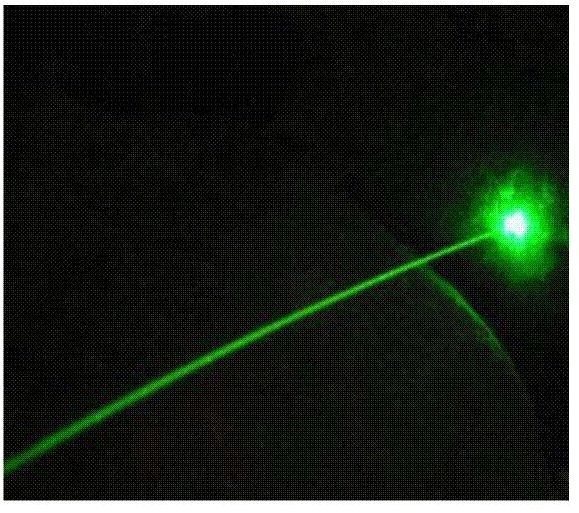
Today lasers, or rather laser beam producing devices, have become very common and are available plentifully in the market in different shapes and sizes. In fact today, the devices are so cheaply available that even school kids use them as toys. Until recently we were only more familiar with the red lasers, but the introduction of the green lasers have made people more enthusiastic about lasing, simply because a green laser pointer beam is more powerful and is able to reach further distances, and the streak is distinctly visible even through dusty air. This becomes possible because the green color (532nm wavelength) is the most visible band in the light spectrum to the human eye.
This feature has made it quite popular among star gazers, who use them for pointing and indicating heavenly bodies. They are also very commonly used in rave parties, discotheques for creating interesting high frequency, high intensity light patterns that enhances party ambiance.
However, the high intensity beam consumes quite a bit of power, and since all commercially available hand held lasers are battery operated, this becomes little concerning as frequent use results in quick exhaustion of the battery. Moreover, if the device involves button cells then the cost of frequent battery replacements may quickly exceed the actual cost of the whole unit. Also, in cases when the unit is intended to be operated from a fixed place, the idea of using an external power supply can become very desirable.
In this article we discuss the construction of a small power supply unit suitable for powering green laser pointers externally and see how we can build a permanent modified green laser pointer by doing this.
Powering Green Laser Pointers Externally
A diode laser may look quite similar to a LED as both require a definite forward voltage drop before they can conduct and are internally made by doping a
semiconductor material. But powering a diode laser, especially a green laser pointer using an AC-DC adapter, is not as easy as it is with a LED. The parameters for powering a diode laser are too stringent and require the utmost care while designing a suitable power supply for them.
The following data will inform you regarding the strict basic parameters required while designing an external power supply for a diode laser.
Current limiting should be absolute and should never exceed the safe level even fractionally. Transients should be well guarded as it can instantly (within nano seconds) kill a diode laser. Transients may also occur during switching the supply ON and OFF, so must be taken care of.
Circuit Description
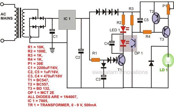
Looking at the figure, the circuit may be understood with the following points:
IC1 along with the associated components forms a well regulated 3 volt DC power supply, but its output is not free from overall and switching transients. Also, it’s not protected from current overshoots.
T1 and its base components make it sure that the circuit does not turn ON instantly, but very gradually, eliminating all possibilities of a switch on transient.
Use of an opto-coupler ensures further safety from transients as its internal LED responds only to definite voltage levels and not to spontaneous ones.
The capacitor across the opto-coupler LED takes care of the power switch OFF transients.
Transistors T2, T3 and P1 together form a very good current limiter circuit and will effectively block any rise in current beyond safe limits (set through P1) to the diode laser.
This circuit may also be used for illuminating more powerful diode lasers than the proposed one.
The present circuit does not include an overheat temperature compensator section as it was not found necessary for a 5mW laser pointer. But, the circuit has enough space to get the required modifications done by integrating with it the attached PD (Photo Diode) normally associated with every diode laser device. We can discuss this through comments.
Modifying a Ready Made Green Laser Pointer Unit
You will have to procure a standard 5mW green laser pointer unit (pen shaped) from the market and slit it open. If you intend to build a completely separate housing for it, then you may remove the driver circuit from it. If you feel much comfortable using the existing pen shaped secured enclosure then perhaps just extending its supply points by connecting small lengths of wire may be quite enough to conclude the modification.
The above steps will need a lot of skill and dexterity; otherwise you may just ruin the whole thing. Please refer the entire procedure for dissecting a readily procured green laser pointer module.
Construction Clues and Testing
The circuit shown here involves standard components, so assembling them won’t require any special attention. Just fix them over a general purpose PCB and do the

necessary connections by soldering as per the circuit schematic. After completing, switch it ON and confirm all the assigned safety output parameters using a digital multimeter.
Once you complete the assembly and testing the power supply circuit, it’s time to integrate it to supply wires of the modded laser unit.
Finally we proceed to the testing of the modified green laser pointer through the configured external power supply circuit.
Do it with the following steps:
Using the original batteries and connecting a milliammeter in series, power up the laser circuit and measure this safe operating value of the current. Note it down.
Remove the batteries and reconnect the laser circuit to the assembled power supply circuit and connect the meter in series with the positive of the supply line.
Do not switch ON the power as yet. Make SURE P1 is kept at its maximum value.
Now switch ON the power. Wait until LED1 lights up fully.
At this point the laser will remain shut-off.
Slowly adjust P1, monitoring the current level over meter and the shine over the diode laser.
Optimize the current level so that it matches exactly to the earlier recorded one.
The laser should also provide maximum glow at this point.
Fix P1 using cyanoacrylate bond to seal its mechanism.
This completes the setting up and testing of the entire circuit of this modified green laser pointer. The power supply circuit may be tried with high power diode lasers and should work equally well.
Remember laser beams can be hazardous if proper safety measures are not observed. Please read this information before you start working with these devices.
Image Courtesy: https://www.greenlazer.com/


