Capacitive power supplies are considered bad replacements for regular or SMPS transformer power supplies because they are not isolated from the AC mains. A simple modification can eliminate this drawback and totally convert them to an almost ideal transformerless power supply.
Editor’s Note: A reader advised us that information regarding the final circuit was outdated and potentially dangerous. This information has since been updated with a disappointing twist to the initial positive outcome the author experienced. Note, that this article is intended for informational purposes only, and intended for experienced electricians. Any electronics project you undertake is done so at your own risk. For more information, please contact the author via his blog at https://homemadecircuitsandschematics.blogspot.in/
Types of Power Supplies
Every electronic circuit inevitably requires a DC power supply to operate. This voltage is basically derived from our domestic AC mains outlet and is stepped down to the required safe level, suitable for the connected circuit. Normally, we utilize an AC – DC adapter for the purpose.
These adapters fundamentally consist of three important components required for the above conversion: the Transformer, the Bridge Rectifier, and the Filter Capacitor. The Transformer is used to step down the applied AC mains through electromagnetic induction. But this voltage is still a low voltage AC and requires rectification and filtration. Rectification is done by the bridge rectifier (comprised of 4 rectifier diodes) and this rectified voltage is further filtered by the preceding electrolytic filter capacitor to produce a clean DC at the output.
The above process of obtaining DC from AC mains voltage is very efficient, invariably used everywhere, and has become quite a standard practice. However, since the size of transformers cannot be compromised, circuits employing these kinds of power supplies tend to become quite heavy and bulky.
SMPS power supplies are becoming pretty popular as they avoid the use of transformers and thus are able to maintain their compactness and weight to the lowest levels. But again, these power supplies are too costly and generally cannot be configured with simpler circuits with low current consumptions as that would make the unit’s cost unnecessarily highly expensive. It’s like attaching a jet engine to a bicycle.
Wouldn’t it be cool if we had a simple, very low-cost and feather-light power supply circuit at our disposal? A simple and an easy option in the form of a capacitive power supply is very feasible and can be pretty handy.
Here we begin by discussing the drawbacks of capacitive power supply circuits and learn how they may be upgraded to form the ultimate “transformerless” power supply, which may be as effective as its other counterparts, yet will be very cheap to build (hardly 30 cents), as well as compact and lightweight. Moreover, it’s permanent.
Despite having many advantages, capacitive power supplies can be dangerous to life as they are not isolated from AC mains and their output may contain lethal mains voltage. A novel way of eliminating this problem has also been discussed here. However, for a circuit which is enclosed inside an insulated box and does not have any output terminating outwards, the above drawback is eliminated anyway.
The circuits described here are all intended to be used for low power applications (100mA Max.), but that’s not a disadvantage as most electronic circuits don’t require current above that figure.
Understanding and Building an Ideal Capacitive Compact Power Supply
CAUTION: ALL THE CIRCUITS PRESENTED HERE ARE AT AC MAINS POTENTIAL, AND THEREFORE EXTEMELY DANGEROUS TO TOUCH IN SWITCHED ON POSITION. UTMOST CARE AND CAUTION IS ADVISED, USE OF A WOODEN PLANK UNDER YOUR FEET IS RECOMMENDED. NEWBIES PLEASE KEEP AWAY.
For more information, see the author’s blog post and the comments on that post, which go in to more detail: [https://homemadecircuitsandschematics.blogspot.in/2011/12/cheap-yet-useful-transformerless-power.html](/tools/For more information, see the author’s blog post, which goes in to more detail: http:/homemadecircuitsandschematics.blogspot.in/2011/12/cheap-yet-useful-transformerless-power.html)
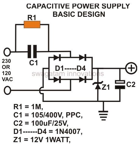
A most basic form of a capacitive power supply is shown in the adjoining figure (click to enlarge).
Let’s try to understand through a stepwise analysis how it functions and how it can be modified and upgraded.
Capacitor C1 does a very important function of keeping the current in check and drops it to a level quite suitable for small electronic circuits (although the voltage remains equal to the mains AC). A bridge rectifier rectifies this voltage and the zener diode brings the voltage to the desired point (12V here). Capacitor C2 filters the output appropriately to produce a clean DC.
This circuit though quite simple and useful, but is accompanied by some drawbacks:
Here, if the phase is connected to the capacitor C1, the mains AC becomes isolated and it’s quite safe to touch the output of the circuit, but if the phase is accidentally connected to the other input terminal, the whole circuit hangs at LETHAL MAINS POTENTIAL, a big and a dangerous drawback.
Since the capacitor C1 behaves quite erratically during input mains fluctuations, it can produce dangerous spikes. These can instantly damage the circuit connected to it.
These drawbacks mean it won’t work well for designs which have terminated outputs or metal cabinets, but won’t matter for units which have everything covered up in a non-conducting housing. However hobbyists must work with this circuit very carefully to avoid any electrical casualty.
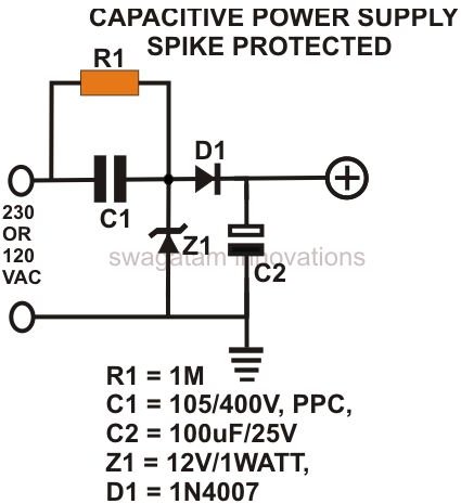
Last but not least, the above circuit allows voltage surges to enter through it, which may cause serious damage to the powered circuit and to the supply circuitry itself.
However in the above design, this drawback has been effectively tackled by introducing a high voltage capacitor after the bridge. This capacitor grounds instantaneous high voltage surges, thus efficiently safeguarding the associated electronics with it.
So, the above power supply configuration is useful only if it’s properly enclosed inside a shock proof box and used in places where the mains voltage is quite stable.
The next circuit shown alongside is an upgraded version of the above circuit. Here, zener diode Z1 has been connected to a rather unusual place, but proves to be very useful. In this position it not only clamps the voltage to 12, but also absorbs the spikes by short circuiting most of it through the negative half-cycles. However, this circuit still is not free from the circulating AC mains voltages in it.
The last circuit shown is what I initially thought to be the most efficient among the above discussed. It is quite similar to the second circuit, i.e., it is spike protected. However, the experiement ended in disappointment.
About 18 months ago, when I initially ran this experiment and tested the circuit using two caps at the two inputs, the line tester showed no leakage mains within the internal circuitry.Therefore, I drew a conclusion that including two caps would seal off the entry of lethal mains in to the proceding electronic circuit.
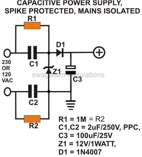
However, several months later, I happened to recheck the circuit and got quite a ‘shock’, literally, when I touched the circuit with my fingers. The lethal mains was present inside the circuit. This was a huge disappointment and the realization that there was no way of eliminating this problem in capacitive PS.
You can read more about this in the comments section of my blog post .
The building of the circuits outlined here does not need much of explanation as it’s just a matter of procuring the shown components and fixing them correctly over a general purpose PCB, or the circuit may be simply built over the PCB of the electronic circuit itself which is being powered through this power supply.


