Controlling a particular electrical gadget through a wireless remote switch can be fun and also very handy. Building such an interesting project at home can be yet more amusing. The complete circuit idea and construction details are furnished here.
Introduction and Circuit Description of the Receiver Board
The circuit of a FM wireless remote switch presented here is very easy to build and can be used to toggle a load anywhere within a radial distance of 50 meters. The above system is controlled through a mini transmitter circuit operating at around 100MHz FM waves. The receiver or the controller board which is the main part of the circuit is actually a readymade FM radio kit, suitably modified for the purpose. This circuit may also be retrieved from a cheap Chinese made headphone FM radio set (will cost not more than a dollar).
Let’s try to understand its circuit description in details.
Since the receiver circuit board is procured readymade, we will just broadly discuss regarding its circuit functioning.
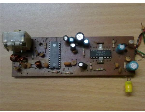
Referring to the figure (click to enlarge), we see that the board primarily consists of two main stages.
The portion comprising of the inductors (can be recognized by the small copper coils), tiny disc ceramic capacitors, gang condenser and the 28 pin IC CXA 1619 is the FM demodulator section. Here, the signal transmitted by the transmitter is received (from antenna) and processed. The embedded information from the signal is demodulated and retrieved.
The other half of the board which consists of the IC 810 and the associated passive components is the audio amplifier stage. The demodulated information from the above stage is amplified here and can be heard through a loudspeaker. The maximum output of this amplifier is around 6 watts into an 8 Ohms speaker.
Normally, the two stages are connected through an electrolytic capacitor and an intermediate variable resistor or a pot (for volume control). The output is also buffered using an electrolytic capacitor, where normally the loudspeaker is connected. However, we won’t discuss the amplification, volume, speaker etc. as they are not involved in this circuit and are immaterial.
The above circuit board is suitably modified for the present idea; let’s learn about the simple manipulations or modifications that have been made to the above board with the following points:
-
The volume control potentiometer is replaced by a preset. Its adjustment and the purpose will be discussed in the “testing” section of the article.
-
At the output, the speaker points are replaced and connected to a buzzer coil (yellow in color at the right end of the FM board).
-
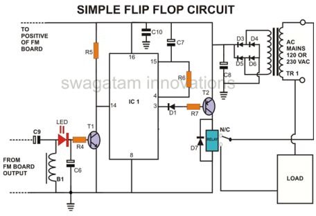
The buzzer coil converts the received amplified demodulated signal into a concentrated pulsating voltage which is used to drive the Flip-Flop circuit (see adjoining figure and click to enlarge). The output from the Flip-Flop toggles a relay and the load connected to its contacts alternately on receiving the subsequent triggers.
Circuit Description of the Transmitter Circuit

The transmitter is in fact the wireless switch through which the above control or the receiver circuit may be switched ON and OFF. The below given discussion will explain regarding its circuit operation.
Looking at the adjoining figure (click to enlarge) we see that the transmitter circuit is very simple in design and uses just one transistor as the main active component. Basically, the configuration is of a standard Colpitts oscillator, where the feedback is received from a voltage divider network formed by C1 and C2.
C1, C2, C3 and the inductor together form the frequency determining components. Here it has been fixed such that the transmitter generates a carrier frequency of around 100 MHz.
The above transmitted carrier frequency can be directly used to activate and deactivate the receiver by alternately toggling the transmitters power supply. But, using only the carrier waves would reduce the range of the transmitter to a great extent and also the accuracy would become too narrow. However, by modulating it through an external frequency its range can be almost doubled.
Here, a small COB (Chip On Board) has been used to create the required frequency and is applied to the base of the transistor. This frequency modulates the carrier waves and makes it much stronger so that it may be received even from a longer distance. These COBs are readily available in the market with a wide range of music, tone, voice messages embedded in them. You may pick and procure any one of them, as here we are interested just in their frequency and not the information.
The next page will provide you with the parts list and construction clues for this wireless remote switch circuit.
Parts List
You will require the following parts for the construction of this wireless remote control circuit:
R1, R3, R4, R6 = 1K,
R2, R5 = 100K,
R7 = 10K,
C1 = 10 PF,
C2, C3 = 27 PF,
C4 = 1 NF,
C5, C10 = 100 NF,
C6, C7, C9 = 10 µF 25V,
C8 = 1000 µF 25V,
T1, T2 = BC 547,
T3 = BC557,
ALL DIODES ARE = 1N4007,
IC1 = 4017,
COIL = 4 TURNS OF 22 SWG WIRE, 7mm IN DIAMETER,
TRANSFORMER = 0 – 12V, 500 mA, input MAINS as per country specifications,
FM receiver assembled kit, or a circuit removed from a FM headphone radio set,
General Purpose Board, Microswitch, 3V button cell, mains cord, LED, etc.
Construction Clues and Testing
The construction is pretty simple as the circuits involved hardly contain any components. Begin by constructing the control circuit first, by inserting and soldering the IC
first, followed by the transistor, relay etc. neatly over the given piece of general PCB. Interconnect their soldered points with the help of the given schematics. Similarly finish building the transmitter circuit with the help of the given circuit diagram. Integrate the control circuit with the FM circuit board (procured readymade) to conclude the construction of the whole system.
Once you complete building and the integration process of the above circuits, its setting and testing may be done in the following manner:
Initially do not connect an antenna to the receiver circuit. Connect and apply a 12 volt DC supply to it and the control circuit board. Due to the typical regenerative “hissing” of the FM receiver, you may find the indicator LED light up and the relay energized. Adjust the preset gradually until the LED just shuts OFF and the relay deactivates. Keep the circuit switched ON in that position.
Now, connect a 3 volt cell (button type) to the transmitter circuit and switch it ON by pressing its push-to-ON switch. Keep it depressed (by putting a heavy object over the switch). It should hopefully start transmitting the modulated signal in the air.
Go back to the receiver circuit; carefully start adjusting the gang condenser. At a particular point on the dial, the receiver should pick the transmitted signal to light up the LED and activate the relay. Fine tune it until the LED produces maximum illumination. Since the receiver does not have an antenna during this instant, you can be sure that the received signal is from your transmitter only and not from the usual FM broadcasts.
Switch OFF both the units. Connect a flexible wire of around 12” as an antenna to the receiver circuit. The transmitter will also need an antenna; an inch of wire will quite suffice.
This wraps up the setting as well as the testing of this wireless remote control circuit.
House the receiver circuit inside an appropriately sized plastic box, allowing the mains cord and the antenna out of the box. Also, make proper arrangements over the box for the fitting of the external socket and the LED.
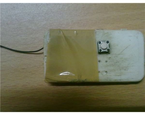
The transmitter circuit should be also enclosed carefully inside a small match-box sized plastic box. The box should have ample space to hold the entire circuit and the 3 V button cell. Also, fix and connect the tiny micro switch at a suitable position to enable easy handling and operation.
The receiver unit may be placed in a suitable position with the respective load connected to it. You may test its efficiency by toggling the button of the transmitter from a distance of around 40 meters away and verify whether the receiver is responding to it or not. Check its consistency by doing it from different corners of your house.


