This article describes how to use an IC TCA-965 as the core of a simple single-chip automatic battery charger.
Simple Battery Charger Features
Finding a reliable, low cost, single chip and easy to build automatic battery charger circuit has always remained quite tantalizing to many electronic enthusiasts and hobbyists. Unfortunately, such a circuit until now has proven not only difficult to find but also difficult to build and customize.
The article presented here should after all end their search here, thanks to the Siemens IC TCA 965 .
Eminently a window discriminator by function, the IC TCA 965 is best suited in places where accurate voltage comparisons are required (which is just what the doctor ordered).
Incorporating this versatile IC in the present circuit of a battery charger has made its construction very simple, easily understandable, and the settings part hassle free.
Let’s try to understand how the circuit actually functions.
Circuit Description
The circuit may be easily understood through the following points:
-
As explained above, the IC TCA 965 here performs the function of a window discriminator, i.e. it monitors the level of voltage in question within a set window or the desired area. If this voltage tends to deviate from the set levels, the output is immediately triggered, which in turn is used either to switch ON or switch OFF the load.
-
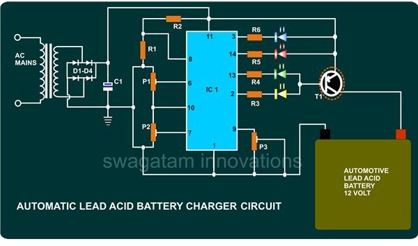
Referring to the circuit schematic (click to enlarge), we see that the upper and the lower “window” voltage thresholds or the references is set through presets P1 and P2 at the pins 6 and 7 respectively.
-
As the supply voltage is not constant, the basic reference cannot be taken from the main supply voltage. A constant stabilized base reference voltage is thus derived from pin #10 of the IC (internally set). Without the facility available at pin #10, the whole system would malfunction.
-
The voltage in question or which is to be monitored is appropriately set at pin #8 through a potential divider network formed by R1 and R2.
-
This reference voltage is compared with the two thresholds set by P1 and P2. As long as the voltage lies in between the two thresholds, pin #13 of the IC is held at logic low.
-
If the battery voltage falls below the lower set threshold set by P1, pin #2 of the IC goes low.
-
If the battery voltage rises above the upper set threshold set by P2, pin #14 of the IC becomes logic low and turning the above pin outs high.
-
The base of the output transistor T1 is connected to the pins 2 and 13. It means that as long as the battery voltage is below the upper threshold, the transistor continues to conduct and switches OFF only when it crosses the upper set threshold level, i.e. when the battery gets fully charged.
-
Since all the outputs are connected via LEDs, the exact states of the battery voltages can be distinctly seen and verified.
-
Pin #9 of the IC provides hysteresis control of the circuit. Hysteresis is just a small glitch or rather a blessing in disguise that can be found in every electronic circuit. Due to this, the outputs of a circuit does not flicker or toggle abruptly at the threshold edges and changes state only after a well-defined level is attained or registered at the inputs. By grounding pin #9, a minimum value of hysteresis can be set.
-
An LED connected to pin #3 will indicate input voltages beyond safe limits (upper and lower).
Parts List
The following parts will be required for the construction of this smart battery charger circuit:
All resistors are ¼ Watt, CFR, 5%, unless otherwise stated.
R1 = 2K7,
R2 = 6K8,
R3, 4, 5, 6 = 470 Ω,
P1, P2 = 10K, LINEAR,
P3 = 100 Ω, LINEAR,
C1 = 2200µ/25V,
LEDs = 5mm, COLORS AS SHOWN IN THE DIAGRAM,
D1, 2, 3, 4 = RATED AT 6 AMPS.
T1 = TIP 32,
IC1 = TCA 965, SIEMENS
TRANSFORMER = 0 – 12V, 5 AMPS. INPUT 120V OR 230V AC AS PER COUNTRY SPECIFICATIONS,
HEATSINK (TO – 220) STYLE,
GENERAL PURPOSE PCB,
SUNDRIES: METALLIC BOX, MAINS CORD, SCREWS/NUTS, FUSE HOLDER, FUSE, SWITCH, ETC.
Construction Clues and Settings
The simple design of the circuit makes the whole assembly just a matter of soldering all the components in place correctly, as per the schematic.
Once the circuit is built, the setting may be done in the following manner:
-
You will need a variable 0 – 24 V regulated power supply unit. Adjust its voltage to about 12.5.
-
Initially keep the slider of the presets P1 and P2 somewhere in the mid ways.
-
Connect the power supply to the circuit, LED connected to pin #13 should light up.
-
Now, decrease the supply voltage to about 11.5 volts and adjust P1 so that the above LED shuts OFF and the LED at pin #2 just lights up. This sets up the lower limit.
-
Next, increase the voltage to about 14.5 volts; this will again make the above LEDs to light up sequentially, indicating the accuracy of the above setting. Adjust P2 so that the LED connected to the pin #14 just lights up, switching OFF the LED connected to pin #13. This sets up the upper limit.
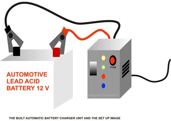
A smart battery charger circuit is fully ready and at your possession. House it appropriately inside a sturdy metal enclosure, strong enough to hold the transformer and the external fittings firmly.
Now, whenever you need to charge your automotive battery (safely), the best way to do it would be to just connect it to this charger and FORGET IT.


