A short circuit in house wiring can be a very rare sight and we don’t worry much as we hardly expect them to happen. But when they occur, they definitely take a big toll. A permanent and a reliable solution to the problem is quite feasible through a simple electronic circuit breaker design. Read on
What Happens During a Short Circuit?
In this article we are going to discuss the simple construction of a very useful circuit breaker device, which can be used to eliminate the possible hazards of an electrical short circuit. But before that, it is interesting to know the possible sources of a short circuit, and the drawbacks of the conventional protection devices.
Domestic mains electric power, available in every house, carries high voltages and currents and thus is potentially very dangerous. Since this power is intended to be used with quite heavy loads like water heaters, geysers, refrigerators etc., the electricity generated at the power stations is specifically and intentionally raised to powerful levels (Mega Watts) so that it can satisfy the required heavy consumptions at each and every house. The various loads (electrical equipment) in our houses are uniformly distributed, therefore current through the conductors (wires) inside the equipment and out are uniformly and safely distributed. Also, because the relevant wires are properly sized to carry the correct amount of current and the connected loads offer appropriate resistances, everything runs normally and peacefully.
During a short circuit, the conductors (wires) offer no resistance, the flowing current finds a free path to travel and hundreds of amperes of current are instantly dumped into the wires. Since domestic wiring is designed to carry a much lower magnitude of current normally, it becomes red hot and can start burning in such a situation. A short circuit may occur because of human error while repairing or amending the existing wiring of a house, animal interference like rats, or the internal malfunctions of an appliance.
Fuses: A Crude Solution
Generally, electrical fuses are employed to avert such dangerous situations. Fuses have a thin conductor inside them, designed to handle load currents up to a particular threshold level, depending upon the maximum load (current consumption) of the house appliances, beyond which it fuses (melts) and breaks the circuit, preventing the possibility of a short circuit.
For example, if the maximum power consumption of a house is expected not to exceed 15 ampere of current, then the required fuse should be selected to “trip” or melt at currents above, say, 17 amperes. And, because the associated wires have a current handling capacity much higher than this level, they will not be damaged.
But fuses are quite primitive in their design, since they have to be replaced when they burn out. Also, replacing them yourself can be pretty confusing and tricky too. A non-technical person often tends to fix the problem by himself in a hurry, and do not understand correct specifications and their fix may pose a serious threat to the system. Even professional electricians are sometimes not technically sound enough and try to solve the problem by replacing the fuse wire with a thicker (higher) capacity fuse in the expectation that the problem of a burnt fuse won’t repeat itself.
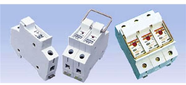
The electromechanical types of circuit breakers are quite efficient but they are costly. Moreover, can it be customized to specific requirements? Nope.
This can be simply solved by introducing a simple electronically designed low cost circuit breaker device, which can not only disconnect the AC mains during a short circuit but can also be reset back to the normal position by just pressing a push button (not to be done until after detecting and correcting the short circuit condition). The next page deals with the circuit and the construction details.
Circuit Diagram and Description
This design for an electronic circuit breaker is very simple in design, uses just a couple of transistors as the main active parts and is easy to construct. Let’s try to understand how the circuit actually works:
-
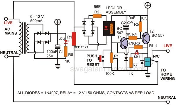
Looking at the adjoining figure (Click to Enlarge), we see that T1 and T2 are configured as voltage amplifiers.
-
Even a voltage as low as 0.4 volts at the base of T1 is enough to trigger T2 into full conduction and activate the relay.
-
A load current sensing resistor R1 is wired in series with the LIVE output of the house wiring via the relay’s N/C contacts.
-
Any short circuit or an equivalent overload at the output will create a small, proportionate magnitude of potential difference across resistor R1.
This potential difference, after rectification, passes through the LED/LDR assembly (home-made opto-coupler), illuminating the internal LED.
-
The light of the LED falling on the parallel connected LDR lowers its resistance enough to immediately provide the required biasing to T1.
-
T2 instantly responds and activates the relay to disconnect the LIVE connection from the output, protecting the house wiring from burning or getting damaged.
-
The relay remains activated and latched in its position because of R7, which holds T1 into conduction even after the LED/LDR assembly is switched OFF.
-
Once the external short is traced and removed, the push button is simply pressed to restore the power back to normal. Pressing the push-button grounds the base drive to T1 from R6, and breaks the latch to deactivate the relay.
-
Capacitor C2 makes it sure that the circuit does not produce false tripping due to stray RF interferences or instantaneous over loads.
-
P1 controls the sensitivity of the circuit.
Parts List
You will require the following components for the construction of this circuit:
All resistors are 1/4 Watt, CFR, 5% tolerance, unless otherwise specified.
R1 = Homemade, see text,
R2 = 56 Ohms,
R3 = LED + LDR assembly, see text,
R4, R7, R8 = 1K,
R5 = 10K,
R6 = 47K,
P1 = 100K Preset
C1 = 100uF/25V,
C2 = 10uF/25V,
All Diodes are = 1N4007,
T1 = BC547,
T2 = BC557,
LD1 = RED LED,
LD2 = GREEN LED,
Relay = 12V/400mA, 20A Contacts
Transformer = 0 - 12V, 500mA, Output = 120/230 V AC,
Push to ON Switch (1no.)
General Purpose PCB = 4 * 3 inches approximately.
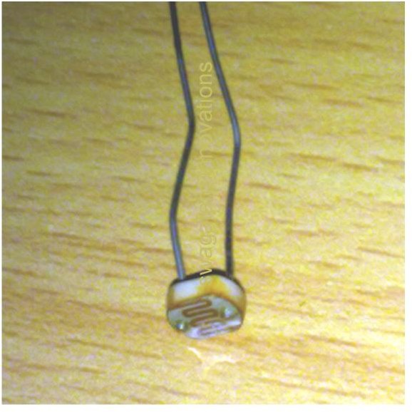
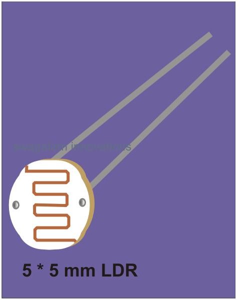
Making the LED/LDR Assembly

The procedure is simple and is done with the following steps:
-
Cut a small piece of general PCB (around 2 square cms.).
-
Bend the LDR and the LED leads at right angles and fix them into the above PCB, facing each other as shown in the figure (Click to Enlarge). Do not cut their extended leads, as they will be used latter on for fixing over the main PCB.
-
Cover the assembly from the top to make it light proof (you may use a cork from a discarded bottle for the purpose).
-
Glue the edges using synthetic enamel paint or nail polish to seal it completely.
The next page discusses the construction and the final testing procedure of this electronic circuit breaker unit.
Building the Main Circuit
Building the main circuit of this short stop circuit breaker is much simpler as it includes just two transistors and few other associated passive components.
The whole circuit assembly may be easily completed by inserting the listed components neatly over a piece of general purpose PCB and soldering their interconnections following the circuit schematic.
R1 may be constructed at home using a piece of iron wire and calibrating it with the help of the following formulas and calculations:
According to Ohm’s law we know that:
E = IR,
Where E is the potential difference developed across R1 = minimum forward voltage drop of the LED used and required to illuminate it.
The value of E may be selected as 2 volts.
I is the maximum load current passing through R1 at which the circuit needs to trip.
Therefore, the final formula becomes R = 2/I.
Its wattage also has to be properly calibrated using the formula:
W = VI,
Where V is the input AC voltage and I is same as above.
The thickness of the wire may be calculated using the formula:
R = ρL/a,
Where ρ = resistivity of iron (ΩMeter), L = length of the wire in Meters and a = area of the conductor (mm2).
Now, if we substitute the above value of R in Ohms law we get:
E = IR = IρL/a,
a = ρIL/E,
The above expression when solved, will give you the exact thickness of R1 (iron wire).
The thickness of R1 may also be selected through some trial and error; the rule of thumb is to make sure that it does not heat up around tripping points (use a sufficiently thick gauge wire).
If R1 is calibrated perfectly through the above methods, it will produce the required 2 volts of potential across itself during the set tripping point. The remaining safety operation of the circuit is also pretty assured after this.
Testing (WARNING: The Circuit Carries DANGEROUS AC Mains Voltage, Extreme Caution is Advised)
For the repeated testing of the prototype I built, I did some actual short circuiting, which led to a lot of sparking and momentary small explosions. Every time the unit worked faithfully and did trip to cut OFF and break the circuit.
But I don’t recommend you try the above method of confirmation (you should not consider it unless you are technically very sound - and - at your own RISK). A safe idea is doing it with these simple steps:
-
In the circuit, remove R1 from its position and keep the relay contacts free from all wiring.
-
Now, connect the unit to the AC mains, and apply 2 volts DC externally to the points where R1 was connected. The circuit should instantly activate and latch up.
-
This confirms the correct operation of the system. LD1 will indicate that the circuit has tripped while LD2 will show the presence of an AC input supply. This should set up the unit quite satisfactorily.
-
After completing the testing procedures, the entire circuit may be housed inside a good looking plastic enclosure with the relevant wires coming out of the box. Also, the LEDs should protrude out through appropriately drilled holes.
-
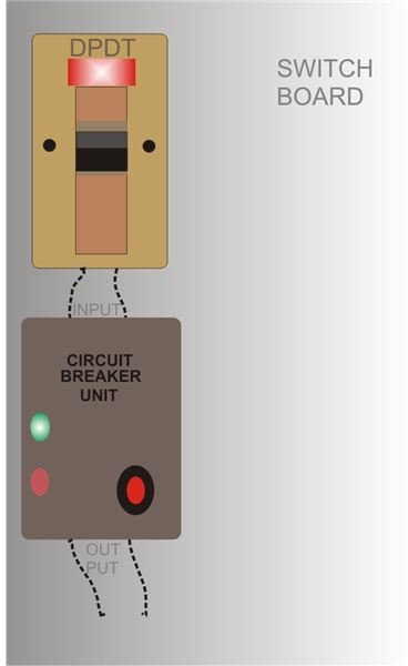
Finally, this short stop circuit breaker unit should be installed (See Diagram and Click to Enlarge) after the DPDT switch over the main switch board.
Your comments are waiting to be heard, so keep posting (comments need moderation, may take time to appear).


