
For electronic newbies it often gets pretty confusing when it comes to integrating relays with an electronic control circuit. We will learn here how to wire a relay through a simple formula, but before that, let’s study a few advantages of using a relay against its other counterparts.
Relay v/s Other Load Switching Components
In electronic circuits, there are various different methods of incorporating an output stage that is able to respond to a small input trigger voltage and switch heavy loads. For example, there are transistors which are able to handle several hundreds of volts without getting damaged, but since these can switch only DC high voltages, they cannot be used for switching high currents and alternating voltages.
To handle alternating voltages, a very useful device called a triac or a SCR is generally utilized. But again these are ineffective with direct voltages as they tend to get latched once a DC crosses from its anode to the cathode.
These drawbacks are due to the characteristic of their internal specific semiconductor compositions and thus they often become quite useless in many applications.
A relay, on the other hand, is totally free from all these hassles and may be considered an ideal component for switching heavy output loads. As these are not semiconductor components, they are not subject to voltage specifications and can handle any type and magnitude of output voltages. Another big advantage of using a relay is that the switching output dangerous potentials are kept completely apart from the delicate electronic control circuit.
Relay, Transistor Wiring
A relay is basically an electromagnet that is used to magnetically pull down a spring loaded shaft so that alternate make and break contacts may be established in between the moving shaft and its two fixed poles. In an absence of a coil voltage each of these poles are normally open (N/O) and normally closed (N/C) respectively.
To power a relay or configure it with an electronic circuit, a small output circuit is generally incorporated and is known as the relay driver circuit.
As shown in the diagram, the section basically consists of a transistor T1, resistor R1 and a flyback diode D1 connected across the relay coil.
Resistor R1 is used to bias the transistor and this biasing voltage is in fact the triggering voltage, which is generally received from a source such as an IC.
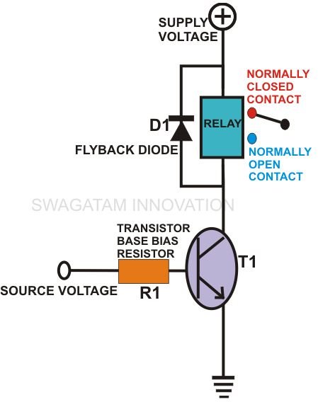
As soon as the transistor receives the trigger voltage, it instantly conducts and activates the relay. This happens because the end of the relay which is connected to the transistor is pulled to the ground potential, so that the entire supply voltage passed through the coil to energize it.
Every inductor has an inherent property of switching back an opposite EMF equal to the magnitude of the supply voltage, the moment it’s switched OFF. This is what exactly happens when the transistor is switched OFF. The relay coil instantly kicks a dangerous EMF back into the transistor. This may cause permanent damage to the transistor unless and until some precautionary measure is adopted. Diode D1 performs the important function of neutralizing this EMF by short circuiting it and avoiding its passage through the transistor.
Calculating the value of a resistor
Now, let’s see how we can calculate the value of the resistor R1. The basic formula is given here:
R1= (Ub - 0.6) × Hfe ÷ Relay Current,
Here Ub = source voltage to R1, 0.6 = minimum transistor biasing voltage,
Hfe = forward current gain of T1 used (150 nominal)
Relay current may be calculated through the following given formula:
Relay I = Resistance of the relay coil ÷ Supply Voltage,
External loads may be connected to the set of relay contacts in two possible ways. If an initial switch ON of the load is required, it may be energized through the N/C contacts. If the load needs to be switched ON after the relay toggles, then it should be powered through the N/O contacts.
Through the above discussion you can easily understand how to wire a relay and how simply the relevant figures may be accurately calculated within minutes.


