Fault finding in complicated mains wirings often becomes a hard nut to crack for every electrician involved in the business. The simple circuit idea presented here can surely help them to get rid of headaches accompanied during such tedious assignments.
Introduction
The simple non-contact AC voltage detector, sensor, tester circuit design presented in this article will be especially useful to all those electrical engineers and electricians who are engaged in difficult electrical circuit designing, repairing and fault finding jobs. A fault inside any AC electrical system is basically caused through a break in the continuity of specific wires and may result in a major breakdown of the whole system. These breaks in the wires are generally caused by aging, short circuits, or in some places rats could be the main cause of these malfunctions.
Our domestic AC mains (house wiring) voltage is made up of alternating currents that keep shifting phase from positive half cycle to negative half cycle. This happens very fast, normally 50 to 60 times per second. Due to this rapid alteration in its phase, alternating currents generate a fair bit of electrical disturbance in the air.
The proposed circuit is actually a very sensitive radio frequency detector and is able to pick even the slightest of electrical disturbance that may be present in the area surrounding it. It is also able to detect the presence of the mains AC voltage from quite a fair distance. Therefore, to find a break inside electrical wiring, the unit’s antenna may be just dragged across the whole length of the suspected wiring. The circuit will just stop, indicating the presence of an AC phase exactly at the point where the break may have occurred, and thus is able to pinpoint the exact place of the cut in the wiring.
How does the Circuit Function?
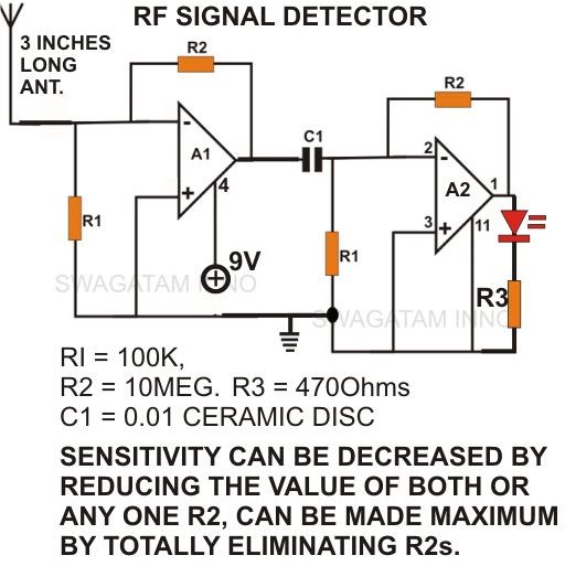
By referring to the circuit schematic we can see that the whole circuit is wired around the IC 324, which is a package of 4 op-amps or quad op-amps.
It forms the heart of the circuit. One of its op amps, A1, is configured as a high gain current to the voltage converter and the second one, A2, is used as a buffer to produce a stabilized output on detection of an AC signal.
(Click Image to Enlarge)
The moment the antenna of the circuit is taken near a conductor carrying AC, the vibrations around the conductor are immediately picked up. These tiny alternating vibrations induce a corresponding current ripple into the circuit, disturbing the overall stability of the circuit.
These input disturbances are instantly amplified by A1 and converted into an output voltage equal to the peak supply voltage of the circuit. The out put is fed to the next amplifier stage via capacitor C1.
On receiving the pulse, A2 further amplifies the signal to produce a visual indication, showing the presence of an AC phase, and vice versa.
The value of R2 may be increased or decreased to correspondingly increase or decrease the sensitivity of the circuit.
Parts List
The following parts may be procured from your local electronic spare part retailer. Just hand over this list to him and he will know exactly what requirements you have and provide you with the items on the list:
All resistors are 1/4 watt, 5%, CFR, unless otherwise specified.
R1 = 100 K,
R2 = 10M (means 10 Mega Ohms - 1Mega Ohms is equal to 1000Kilo Ohms and 1Kilo Ohms is equal to 1000 Ohms. Ohm is the basic unit of measurement for resistors.
R3 = 470 Ω,
C1 = 0.01microFarad, CERAMIC, DISC
A1, A2 = IC 324,
BATTERY 9V PP3,
GENERAL PCB,
PLASTIC ENCLOSURE
Construction Clues
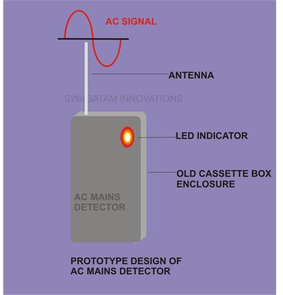
The circuit of this non-contact AC voltage detector can be easily built within a small piece of general PCB with the help of the given circuit schematic. Just insert all the procured components into the PCB, bend their leads to interconnect, and solder the relevant points. The whole assembly, along with a 9 Volt battery, may then be enclosed inside a small plastic container with only its antenna protruding out of the box. The antenna may be any conductor 3 inches in length, fixed externally to the box and connected internally to the circuit.
(Click Image to Enlarge)
While testing, do not let any of your body part touch the antenna of the unit, as that will produce a false indication.
The unit is now ready and may be used to trace out the AC voltage interruptions within the wiring in question.


